CLEANING & MAINTENANCE
24 P/N 595390-01 Rev D 202009
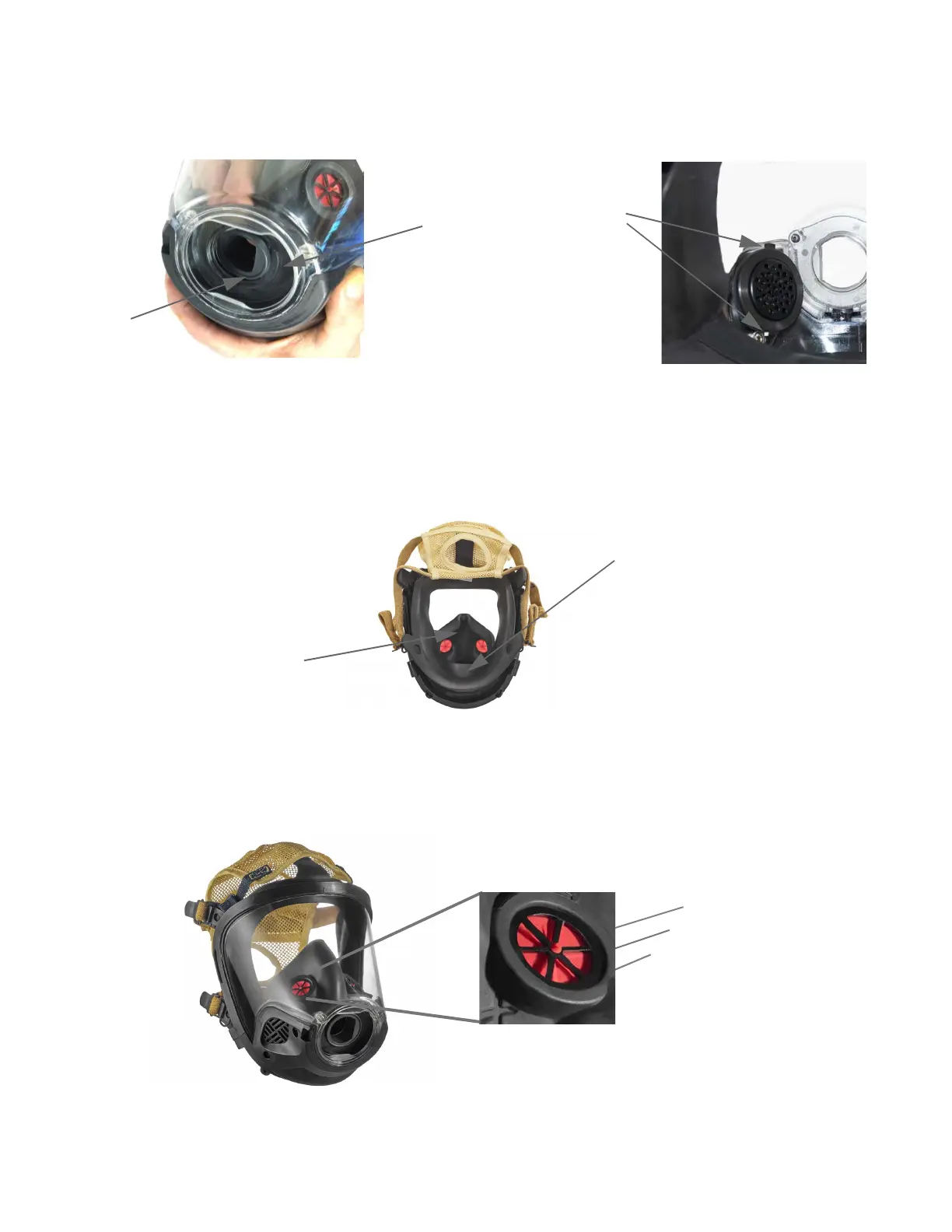
3 Stretch each 2" diameter hole in the nosecup onto the end of the voicemitter ducts and posts until fully around
each duct. See Picture B in Figure 4-2.
Figure 4-2 Pressing the nosecup tube
4 Check the nosecup to verify the following:
• The inhalation check valves are facing up and toward the inside of the nosecup.
• The nosecup is properly seated in the facepiece air deflector and around the voicemitter ducts and posts.
• The nosecup is inside the faceseal (away from the wearer). See Figure 4-3.
Figure 4-3 Nosecup inside the faceseal
To remove and install the nosecup inhalation valves
Typically, the two inhalation valves installed in the nosecup assembly are not removed during maintenance; however,
if replacement is required, proceed as follows:
1 Grip the nosecup inhalation valve disc with your fingers and pull of the valve seat. See Figure 4-4.
Figure 4-4 Valve assembly
Voicemitter duct
posts
A
B
Air deflector
Nosecup tube
Faceseal
Nosecup
Stem
Valve seat
Valve disc