USER’S MANUAL
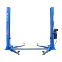
4.3 FLOOR
The lift must be installed on a horizontal concrete bed
a minimum thickness of 200mm built and a resistance
≥30N/mm
2
.
The floor must also be flat and level (10mm of tolerance
for leveling). Consult the manufacturer with regard
special applications.
Fig. 30
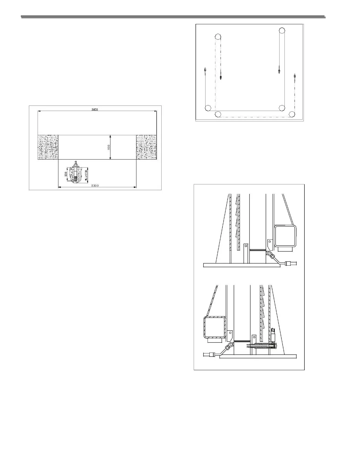
◆ Connect the high-pressure hose according to Fig. 31.
First connect the hose with tri-joint under the main
column and the bend under the sub-column. Fix them
after upright the columns.
Fig. 29
4.4 ASSEMBLING
WARNING
DURING INSTALLATION ONLY AUTHORISED
PERSONNEL IS ALLOWED.
To assemble the lift, the weight of the various parts is to be
considered, in order to provide a lifting machine with the
minimum capacity 500kg and max. lifting height of
2900mm.
Before starting to assemble the lift, check the crate contains
all the needed material.
4.4.1 POST ASSEMBLING
◆ Install both boards on the bases, keep the main
column upright, and put the stiffs which are no less
than 100mm on the upside for the convenience of
installing the safety device, cable, hose and wire.
◆ Install the balance cable according to Fig. 30. The
cable also can be crossed from the hole on the board
before the fixing of both columns.
Fig. 31
◆ Hold up both columns (keep the carriage lock and in
the same level), and then fix the bolts on the base.
◆ Install the safety devices.
◆ Adjust both cables and keep the carriage in balance.
-12-