USER’S MANUAL
◆ Block the spring ring at the end of the pin.
WARNING
End-user should confirm that the over load device must
be connected before the electrical power connected to lift.
4.4.5 INSTALL THE COVER PLATE
Install the cover plates at the chassis by 4 pieces M8×16
bolts.
Fig. 35
4.4.3.3 The wires should be fixed by nylon pitch.
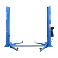
4.4.3.4 Close the cover of the junction box. Press the up
push button (Fig. 35), the motor rotation direction should
be the one shown by the arrow on the pump.
BEWARE: The pump rotating for a long time in the
wrong sense may cause itself serious damages.
4.4.3.5 Make sure that the post end limit switch work
properly by pressing them manually.
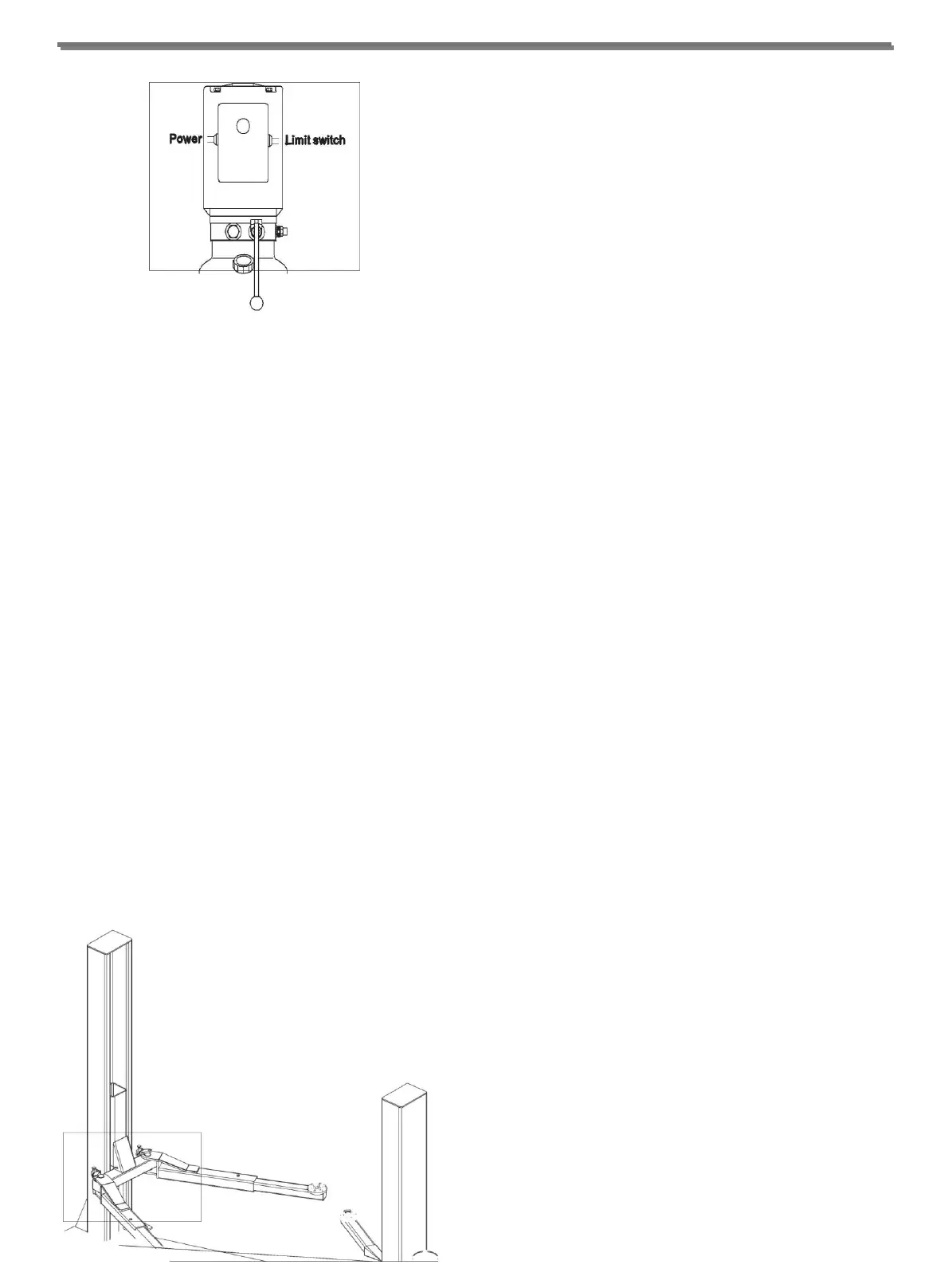
4.4.4 ARM ASSEMBLING
◆ Press the up push button, raise the carriages to a
height of about 70cm off the ground, then press the
manual lowering lever until the carriages rest on the
safety wedge. CUT OFF THE POWER SUPPLY TO
THE LIFT.
◆ Grease the holes φ40 on the arms ends.
◆ Mount the arms into the carriage supports and insert
the dowel pins into the support holes as shown in Fig.
36. Notice the entry of both arms is the same with the
entry of the vehicle.
Fig. 36
4.4.6 INSTALL SPRING SCREW
◆ Make 14 drills on the basement with a helical concrete
bit with a diameter of 18mm to a depth to 130mm.
Use the basis pad as a drilling template.
◆ Install the screw according to Fig. 29.
4.5 TESTING AND CHECKS TO PERFORM
BEFORE START-UP
4.5.1 MECHANIAL TESTS
◆ Attachment and tightness of bolts, fittings and
connections
◆ Free sliding of moving parts
◆ Clean state of various parts of the machine
◆ Position of the protection device
◆ Arms blocking device
4.5.2 ELECTRIC TESTS
◆ Connection comply with diagrams
◆ Machine earth connections
4.5.3 OPERATING OF THE FOLLOWING DEVICES
◆ Rise limit switch
◆ Manual lowering valve
4.5.4 HYDRAULIC OIL TEST
◆ Sufficient oil in the tank
◆ No leaks
-14-