USER’S MANUAL
◆ 1 hydraulic unit (Fig. 2-7), on the command side, to
set the cylinders run.
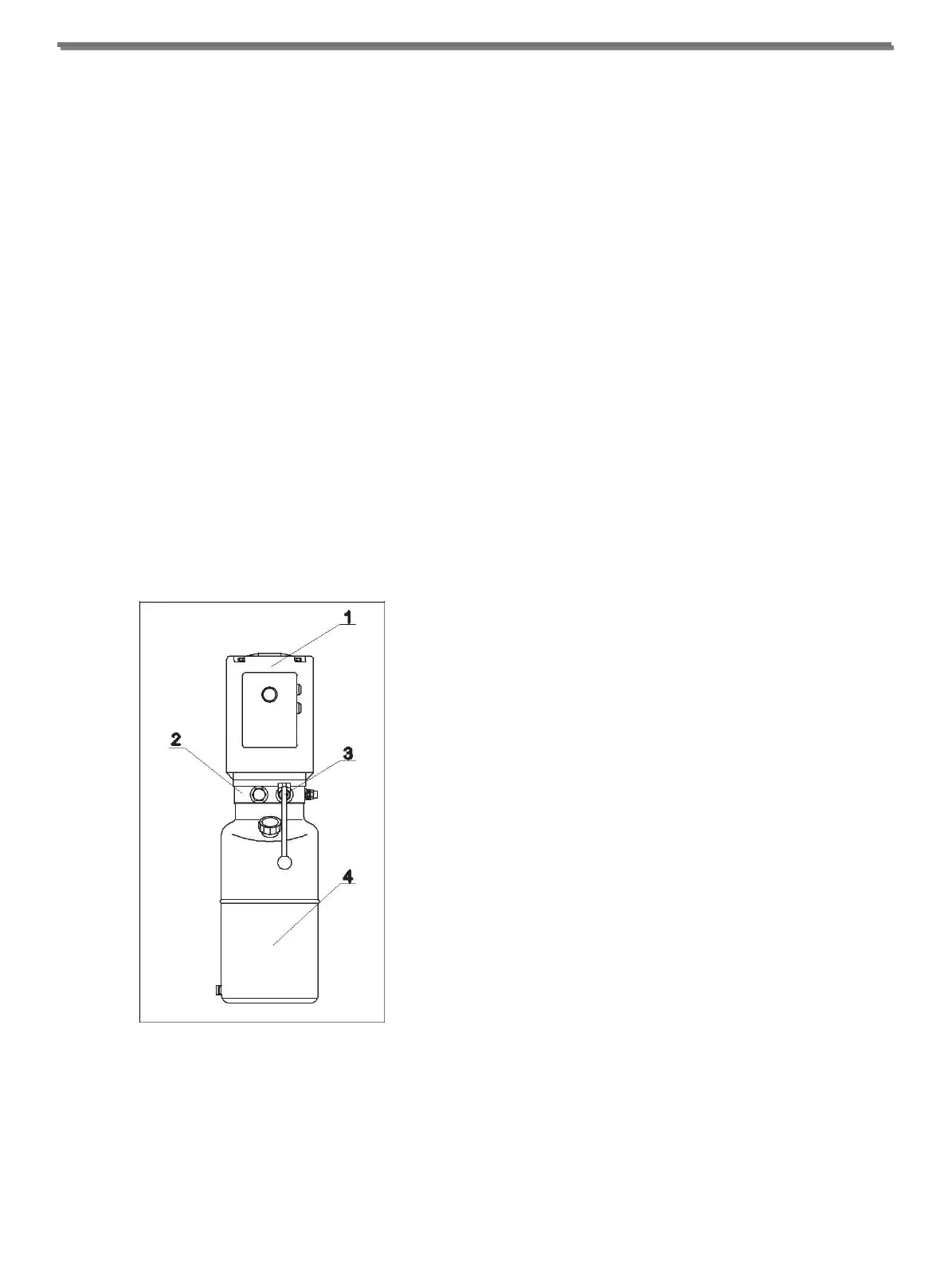
1.4 HYDRAULIC POWER UNIT
The hydraulic power unit consists of:
◆ An electric motor (Fig. 3-1);
◆ A geared hydraulic pump (Fig. 3-2);
◆ Descent hand-valve equipped with a manual oil drain
valve; (Fig. 3-3) (see the use and maintenance
chapter)
◆ A maximum pressure valve;
◆ Oil tank (Fig. 3-4);
◆ An oil delivery and return flexible pipe to the
cylinders feeding circuit.
Note: The oil delivery pipe may be under pressure.
Fig. 3 Hydraulic Power Unit
1.6 SAFETY DEVICES
The safety devices include:
◆ Mechanical safety device for carriage;
◆ Arms locking system;
◆ 4 foot guards on the arms;
◆ A synchronous device to control the carriages
movement;
◆ End limit switch;
◆ General electric safety devices;
◆ General hydraulic safety devices.
These safety devices will be described in further detail in
the following chapters.
-2-