EasyManua.ls Logo

AA4C AA-2PFP45 - 2.6 Hydraulic Oil Hose Connection Diagram; 2.7 Vehicle Weight and Size; 2.8 Maximum Dimensions of Vehicles to be Lifted

AA4C AA-2PFP45
30 pages
Print Icon
To Next Page IconTo Next Page
To Previous Page IconTo Previous Page
Loading...
USER’S MANUAL
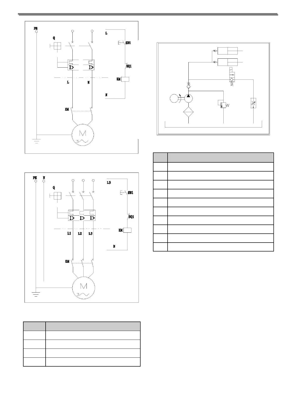
Fig. 5 1Ph Electrical Diagram
Fig. 6 3Ph Electrical Diagram
CODE
DESCRIPTION
Q
Circuit Breaker
SB1
Lift Button
SQ1
Limit Switch
KM
AC Contactor
Table 4
2.6 HYDRAULIC OIL HOSE CONNECTION
DIAGRAM
1
2
3
4
D
5
6
8
9
7
10
Fig. 7
S/N
DESCRIPTION
1
Lock valve
2
Operating Cylinder with simple effect
3
Manual lowering valve
4
Check valve
5
Motor
6
Pump
7
Filter
8
Pressure relief valve
9
Flow control valve
10
Tank
Table 5
2.7 VEHICLE WEIGHT AND SIZE
Lift rack can be adapted to virtually all vehicles no heavier
than 4000kg, the dimensions of which do not exceed the
following:
Max width: 2400mm
Max wheelbase: 3000mm
2.8 MAXIMUM DIMENSIONS OF VEHICLES
TO BE LIFTED
The underbody of cars with low ground clearance may
interfere with the structure of the lift. Pay particular
attention in the case of low body sports cars.
-4-