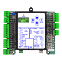
11RSMVQ Technical Guide
INPUTS AND OUTPUTS
RSMVQ Inputs and Outputs
RSMVQ Inputs and Outputs
+5 - VDC Power
This output is a 5 VDC output that supplies power to the Head
Pressure Transducer 1.
HP1 - Head Pressure Transducer 1
The Head Pressure Transducer is used to measure Head Pressure
at the discharge line. This Head Pressure is used to drive
Condenser Fan 1 to maintain a given Head Pressure Setpoint.
+5 - VDC Power
This output is a 5 VDC output that supplies power to the Head
Pressure Transducer 2.
HP2 - Head Pressure Transducer 2
The Head Pressure Transducer is used to measure Head Pressure
at the discharge line. This Head Pressure is used to drive
Condenser Fan 2 to maintain a given Head Pressure Setpoint.
TEMP1 - Discharge Temperature Sensor 1
This sensor is the Discharge Line Temperature Sensor for Circuit 1.
It is the G010470 Thermistor 10K ohm strap-on pipe sensor.
It is strapped to the discharge line immediately after the VFD
compressor and is used as a safety against high compressor
temperatures. Units with Copeland™ VFDs have the Discharge
Line Temperature Sensor wired directly to the drive. Units with
Danfoss VFDs will have a Discharge Line Temperature Sensor
wired to TEMP 1 of the RSMVQ.
TEMP2 - Saturation Temperature Sensor 2
This sensor is the Suction Saturation Temperature Sensor for
Circuit 2. It is the G049490 Thermistor 10K strap-on pipe
sensor. It is strapped to the evaporator coil immediately after
the Thermal Expansion Valve (TXV) and is used to measure the
Suction Saturation Temperature of the second circuit.
BI1 - Compressor Status 1
A wet contact closure (24 VAC) on this input indicates
Compressor 1 is running. Typically, the source for this is a relay
output from the VCCX2. If BI1 opens, a compressor alarm will
be generated. Compressor 1 relay needs to be congured on the
VCCX2 as “A1 Compressor Run Status.”
BI2 - Compressor Status 2
A wet contact closure (24 VAC) on this input indicates
Compressor 2 is running. Typically, the source for this is a relay
output from the auxiliary contact on the compressor starter. If
BI2 opens, Compressor 2 Enable relay and Compressor 2 High
Speed Enable relay will de-energize and a compressor alarm
will be generated.
NOTE: The binary inputs require wet contacts (24 VAC
only) to recognize an active input. If you provide
dry contacts, the contact closure will not be
recognized.
AO1 - Condenser Fan 1 VFD Signal
This is a direct acting output signal that is used to modulate the
Condenser Fan 1 VFD (0-10 VDC signal) on an air cooled unit.
AO2 - Condenser Fan 2 VFD Signal
This is a direct acting output signal that is used to modulate the
Condenser Fan 2 VFD (0-10 VDC signal) on an air cooled unit.
EXV-1 - Electronic Expansion Valve
The EXV-1 is the communications port for EXV setpoints and
status communications.
EXV-2 - Electronic Expansion Valve
The EXV-2 is the communications port for EXV setpoints and
status communications.
RLY1 - Compressor 2 Enable
This relay turns on Compressor 2.
RLY2 - Compressor 2 High Speed Enable
This relay enables high speed on Compressor 2.
RLY3 - Condenser 1 Enable
This relay enables Condenser Fan 1.
RLY4 - Condenser 2 Enable
This relay enables Condenser Fan 2.

 Loading...