4
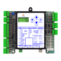
RSMVQ2R Technical Guide
FIGURES AND TABLES
TABLES
Table 1: RSMVQ2R Controller Electrical and Environmental Requirements .................................................................. 7
Table 2: RSMVQ2R Inputs and Outputs ............................................................................................................................10
Table 3: Compressor Speed / Head Pressure ...................................................................................................................14
Table 4: Navigation Key Functions .......................................................................................................................................15
Table 5: Editing Key Functions .............................................................................................................................................15
Table 6: 0-5V Temperature Sensor - Voltage & Resistance for Type III Sensors ......................................................... 29
Table 7: Head Pressure Transducer Chart .........................................................................................................................30
Table 8: Compressor Type Specication Table ..................................................................................................................34
FIGURES
Figure 1: RSMVQ2R Dimensions ............................................................................................................................................6
Figure 2: RSMVQ2R Inputs Wiring .......................................................................................................................................... 8
Figure 3: RSMVQ2R Outputs Wiring .......................................................................................................................................9
Figure 4: Danfoss VZH028, VZH035, VZH044 Envelope ................................................................................................. 13
Figure 5: Danfoss VZH052 and VZH065 Envelope ............................................................................................................13
Figure 6: Copeland ZPV0662E Envelope .............................................................................................................................13
Figure 7: Copeland ZPV0962E Envelope .............................................................................................................................13
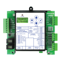
Figure 8: LCD Display and Navigation Keys ........................................................................................................................ 15
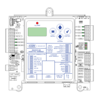
Figure 9: RSMVQ2R LED Locations .....................................................................................................................................28
Figure 10: Prims 2 Single Condenser Module A Conguration ...........................................................................................31
Figure 11: Prims 2 Two Condensers Module A Conguration ............................................................................................. 32
Figure 12: RSMVQ2R Module A Compressor Type ..............................................................................................................33
Figure 13: Miscellaneous Setpoints Screen - Copeland Model Selection ......................................................................... 33
Figure 14: Update Copeland ..................................................................................................................................................... 33
Figure 15: RSMVQ2R Unit Tonnage Selection ......................................................................................................................34
 Loading...