8
RSMVQ2R Technical Guide
WIRING
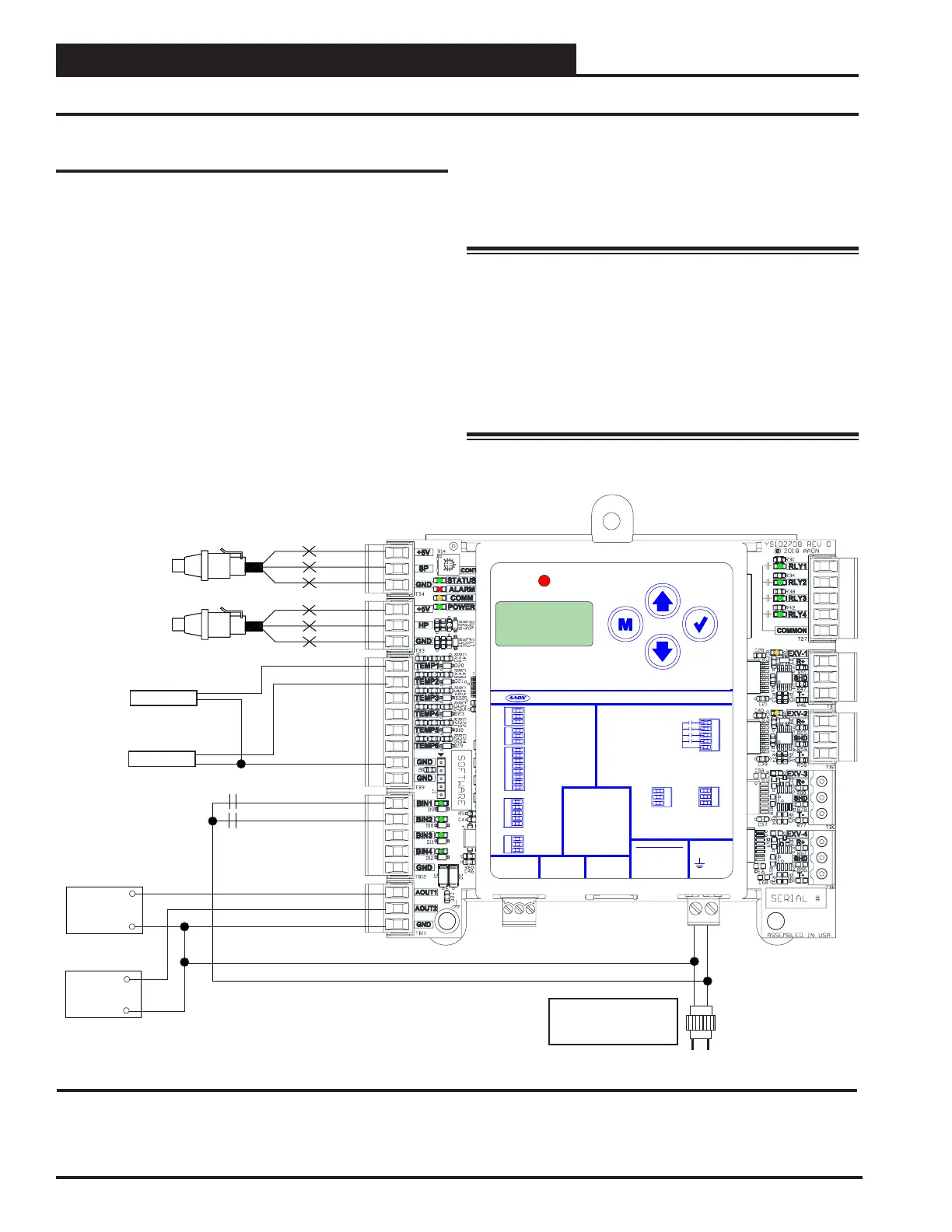
RSMVQ2R Inputs Wiring
RSMVQ2R Wiring
The RSMVQ2R connects to the VCCX2 Controller using an
EBC E-BUS cable. Only one RSMVQ2R can be connected.
There are two E-BUS Expansion Ports which allow the use of
communicating sensors and the E-BUS Modules.
The RSMVQ2R uses four analog inputs, two binary inputs, four
relays, and two analog outputs. See Figure 2, this page for inputs
wiring and Figure 3, page 9 for outputs wiring.
Head Pressure Control
The RSMVQ2R can monitor the Head Pressure Transducers and
control Condenser Fans to maintain a Head Pressure Setpoint.
The Condenser Fans will be controlled with a 0-10 VDC output
signal.
Condenser and Compressor Conguration
Options
Please see pages 31-34 for Condenser and Compressor
Conguration details.
WARNING: Observe Polarity! All boards must be wired
with GND-to-GND and 24 VAC-to-24
VAC. Failure to observe polarity will result
in damage to one or more of the boards.
Expansion modules must be wired in such
a way that the expansion modules and the
controller are always powered together. Loss
of power to the expansion module will cause
the controller to become inoperative until
power is restored to the expansion module.
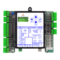
Figure 2: RSMVQ2R Inputs Wiring
18-30
VAC
GND
Line
Voltage
Size transformer for
correct total load.
RSMVQ2R = 18 VA
HP
GND
+V
BK
RD
WH
COMP STAT 1
COMP STAT 2
BIN1
BIN2
GND
COM
+
Condenser Fan 2
AOUT1
AOUT2
COM
+
Condenser Fan 1
TEMP 1
TEMP 2
GND
HP
GND
+V
BK
RD
WH
Head Pressure
Sensor
(by others)
Head Pressure
Sensor
(by others)
Discharge Temp
Sensor 1
Saturation Temp
Sensor 2
ALARM
UP
DOWN
ENTERMENU
AAON P/N: ASM02652
+24 VAC
GND
RELAYCONTACT
RATING IS 1AMP
MAX @ 24 VAC
CONDENSER 1
COMP 2 ENABLE
COMP 2 HI SPEED
ANALOG OUTPUTS
COMMON
RELAY OUTPUTS
LABEL P/N:
G068350
COND FAN 1
COND FAN 2
GND
24 VAC POWER ONLY
WARNING! POLARITY
MUST BE OBSERVED
OR THE CONTROLLER
WILL BE DAMAGED
CONDENSER 2
+5 V
DISCHARGE TEMP 1
COMP STAT 1
H1P
SATURATION TEMP2
COMP STAT 2
GND
NOT USED
GND
NOT USED
GND
BINARYINPUTS
MODBUS
RSMVQ2R
www.aaon.com
HEAD
PRESSURE
SENSORS
DUAL
E-BUS
EXP VALV E1
+5 V
H2P
GND
NOT USED
NOT USED
GND
NOT USED
EXP VALV E2
R+
T-
SH
SHD
T-
R+
SHD
T-
R+
EXP VALV E3
NOT
INSTALLED
EXP VALV E4
NOT
INSTALLED
EACH EXP VALVE IS INDIVIDUALLY
ELECTRICALLY ISOLATED
NOT USED
 Loading...