15
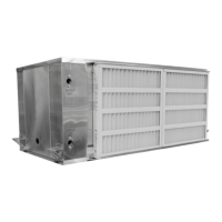
Verify the top of the vibration grommet is
inserted into (or through) the hole provided
in the hanger bracket, as pointed out in
Figure 4.
Figure 4 - Vibration Grommet Installation
The threaded rod and nut must be
adequately sized to support the total unit
weight. Avoid installing units directly above
or adjacent to sound-sensitive areas.
Note: Ductwork must be supported
independently from the unit. The unit must
not support supply and/or return ductwork.
Allow adequate service clearances as shown
on the unit nameplate and unit drawing.
Consult your local building codes for
additional service clearance requirements.
Allow adequate space for piping access and
panel removal. Water piping is on the
compressor end and condensate drain
connections are located on the opposite end.
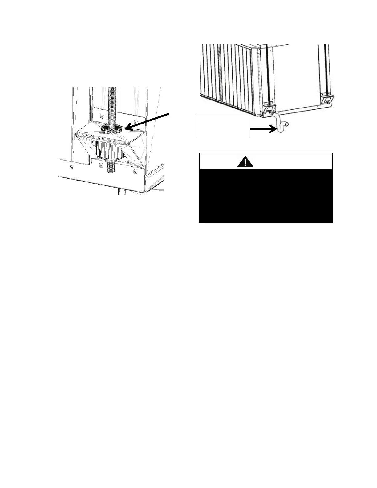
Figure 5 - Condensate Drain Piping
Floor Mounted Units
Make sure the unit is level and mounted on a
field supplied platform with a minimum
height to allow for proper depth of the
condensate line p-trap. Other installation
provisions may be necessary according to
job specifications.
It is recommended that a vibration isolation
pad be used when floor mounting a unit
Condensate Drain Piping
A p-trap and drain line must be installed on
horizontal units, with the p-trap not to
exceed 6” from the drain connection. Use
the same pipe size or larger as/than the drain
connection and pitch downward toward
drain. Use an air break in long runs of
condensate lines. Note: All horizontal units
require a field installed p-trap.
Emergency drain pan is
recommended for all applications
where a risk of water
surrounding structure or furnishings.
Refer to local codes.
 Loading...
