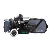
35mm 4-Perf camera, working with the software version number
2.08.
2.9.13 Total Footage Recall
To find out total footage run through the camera since manufacture
install, hook up a battery onto the camera body, press SYNC and
flip the switch to TEST. The footage displays in thousands of
images.
2.9.14 Warning
If for some reason the camera loses its programming parameters,
“UNADJUST” will flash regularly. leaving the camera functionning.
The TCXO then uses default frequency adjustment, insuring a
TimeCoding precision of 10
-4
instead of 10
-6
.
2.10 LED INDICATORS
The AATON 35-III utilizes LED indicators in three locations to convey
information: in the viewfinder and on both left and right sides of the
camera body.
2.10.1 Position and Meaning of the Diodes
• Two yellow diodes, placed on both right and left sides of the came-
ra body indicate that the camera is either on Test or on Run mode.
• Two red diodes, placed on both right and left side of the camera
body, and a third one, visible from the view finder, display a special
warning.
2.10.2 Camera Test Indicator
● Yellow diode is on.
●●● Red diode is blinking fast.
2.10.3 Camera Run Indicator
●Yellow diode is on.
❍ Red diode is off.
38