103 ACS2000 AFE 1MVA UM 3BHS297030 ZAB E01 REV. J
6.10 Auxiliary power, control and
serial communication cables
6.10.1 Further information
The power feed for the auxiliary
supply must be protected with a
suitable circuit protection rated
for the inrush current. For infor-
mation, see utility consumption
list of the drive.
6.10.2 Preparing the cable entry and the cables
Determining the cable length
1. Determine the required length of a cable
between the point of entry and the connection
point inside the cabinet.
2. Cut the cable to the required length before con-
nection.
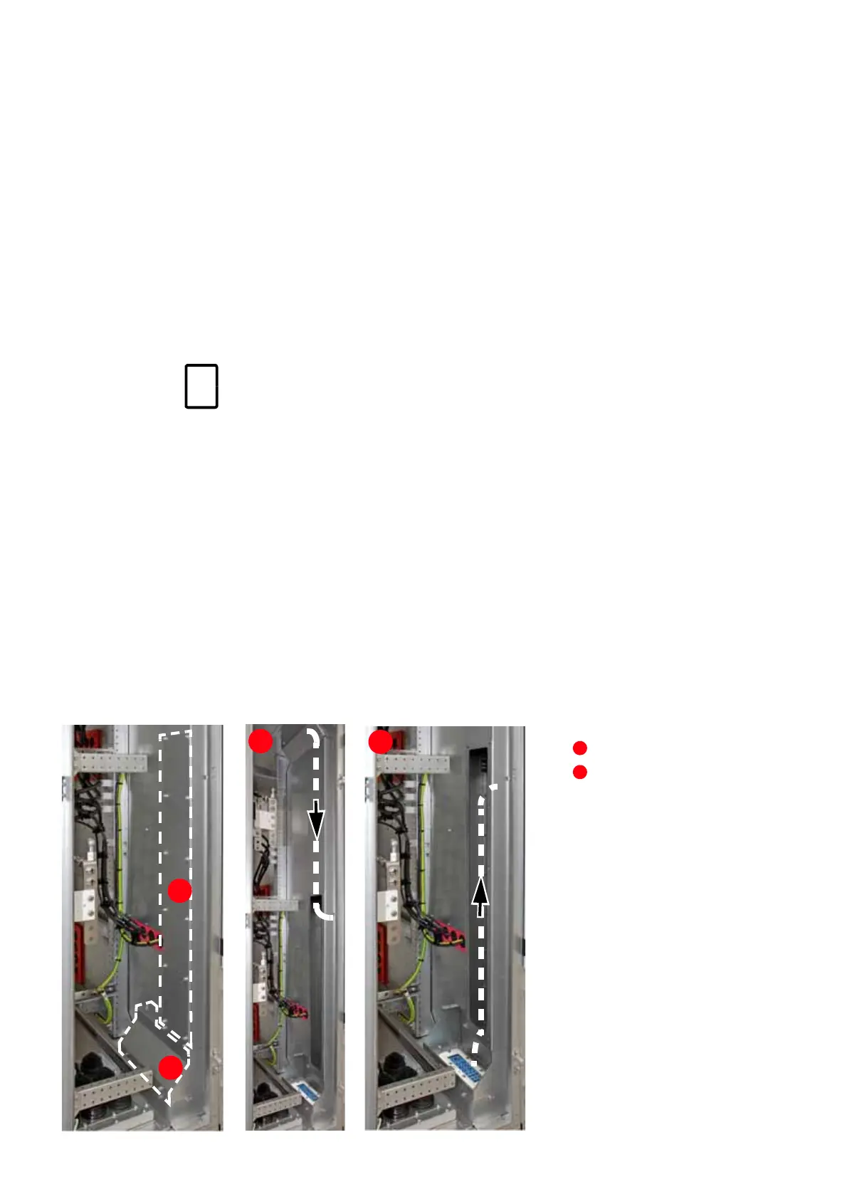
Routing the cables
Top and bottom entry
• To facilitate cable routing, remove the cover
above the cable transit (6-9: 1), and the cover of
the cable duct (6-9: 2).
• Rout the cables as illustrated to the customer
terminals in the control compartment.
See Appendix C – Mechanical drawings
for information on:
• Project-specific cable entry
• Dimensions between point of cable
entry and terminals
See Appendix D – Wiring diagrams for
information on:
• Conventions for cross-references and
device identification
• Terminal designations
Entry from top
Entry from bottom