Terminal allocation
X1A:1 L- 0 V supply in
X1B:1 L+ 24 V (DC) supply in
X1B:2 L+ 24 V (DC) supply out
X1B:3 SA Redundant power supply "A" monitoring input
X2:1 + + Signal
Customer connections
X2:2 - - Signal
X2:3 SH Shield
X2:4 SH Shield
Terminal allocation
X2:1 D(P) Data positive
Customer connections
X2:2 D(N) Data negative
X2:3 DG Data ground
X2:4 SHF Shield AC ground via RC filter
X2:5 SH Shield ground direct
X2:6 0 V
Power supply (24 V (DC) +/- 10 %)
X2:7 +24 V
X2:8 PE Ground
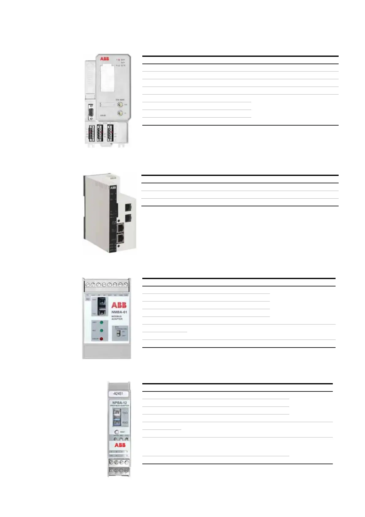
NPBA-12 terminal assignment
X1:1 A Data negative (conductor 2 in twisted pair)
Customer
connections
X1:2 B Data positive (conductor 1in twisted pair)
X1:3 A Data negative (conductor 2 in twisted pair)
X1:4 B Data positive (conductor 1in twisted pair)
X2:5 24 V
Power supply (24 V (DC) +/- 10 %)
X2:6 0 V
X2:7 DG Cable data ground (optional 3rd conductor)
Connected to module ground via a 1MOhm / 15 nF
RC network
Customer
connections
X2:8 SH Cable shield. Internally connected to module