Update Notice
5
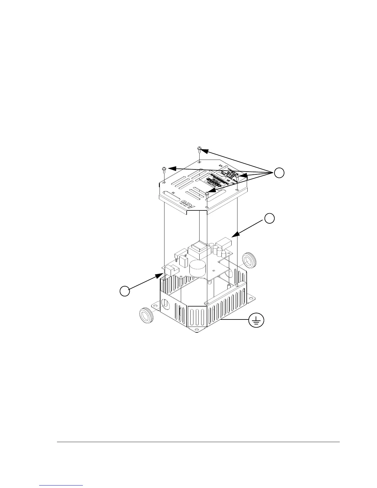
Connect the optional ASTO board as follows:
• Remove the cover of the enclosed ASTO unit by undoing the fixing screws (1).
• Ground the ASTO unit via the bottom plate of the enclosure or via terminal X1:2
or X1:4 of the ASTO board.
• Connect the cable delivered with the kit between terminal block X2 of the ASTO
board (2) and drive terminal block X41.
• Connect a cable between connector X1 of the ASTO board (3) and the 24 V
source.
• Fasten the cover of the ASTO unit back with screws.
Note: Location of the X41 terminal block varies according to the drive frame size,
see page 67.
Note: Maximum cable length between ASTO terminal block X2 and drive terminal
block is restricted to 3 m.
For technical data, see section ASTO-11C in chapter Technical data.