Chapter 2 – AC 80 Hardware and Connections
2-6 AC 80 User’s Manual
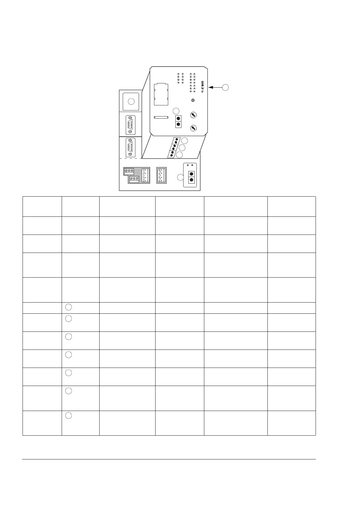
AC 80 Connections
*Colour codes: Grey: Transmitter, Blue: Receiver.
Name
Terminal
(see above)
For connection of Cable Data Remark
Power
Supply
L+ L+ SA
L– L– SB
Power Supply 0.2 to 2.5 mm
2
+24 V d.c.
(19.2 to 30 V)
Redundancy
available
AF 100 AF100 1
AF100 2
AF 100 (Advant
Fieldbus 100)
Screened twisted
pair
Max. length 750 m
Max. no. of nodes 32
Redundancy
available
Service Ch1
(Terminal
Board X4)
PC (Configuration
and Maintenance)
RS-232 RS-232 signal levels
Max. comm. 20 kbit/s
D-sub
9-pole
Panel/Printer Ch2
(Terminal
Board X5)
CDP 80 Ctrl. Panel
Alarm printer
GOP Panel
RS-485 Protocol: Modbus
RS-485 signal levels
Max. comm. TBD
D-sub
15-pole
Battery Battery – Lithium 3.6 V 900 mAh 14.5 × 25 mm
Tool*
(NCB CH3)
PC tools
(Drive
Debug
)
Fibre optic Protocol: DDCS 10 MBd optical
components
DriveBus*
(NCB CH0)
ABB drives
Branching units
Fibre optic Protocol: DDCS,
DDCSe
10 MBd optical
components
Special I/O*
(NCB CH1)
NBIO-21, NBIO-31,
NPCT-01, DSU
Fibre optic Protocol: DDCS 5 MBd optical
components
Fieldbus
Adapter*
(NCB CH2)
Fieldbus Adapters,
e.g. NPBA-80
Fibre optic Protocol: DDCS 5 MBd optical
components
Optical
ModuleBus
(optional)*
TB820 Modems
ABB drives
Fibre optic Protocol: DDCS
Max. 12 I/O units in
max. 7 clusters
Requires
TB810/811
Optical Port
Electrical
ModuleBus
S800 I/O units C/4 Plug-in Max. 12 I/O units
24 V supply 1.0 A
5 V supply 2 A
1
2
3
4
5
6
7
8
9
0
1
2
3
4
5
6
7
8
9
0
L+ L+ SA
L– L– SB
Ch1
Ch2
SERVICE
AF100 21
Tx
Rx
+
–
SH
SH
+
–
SH
SH
Tx
Rx
3
4
5
6
2
7
1
1
2
3
4
5
6
7