Chapter 2 – AC 80 Hardware and Connections
2-12 AC 80 User’s Manual
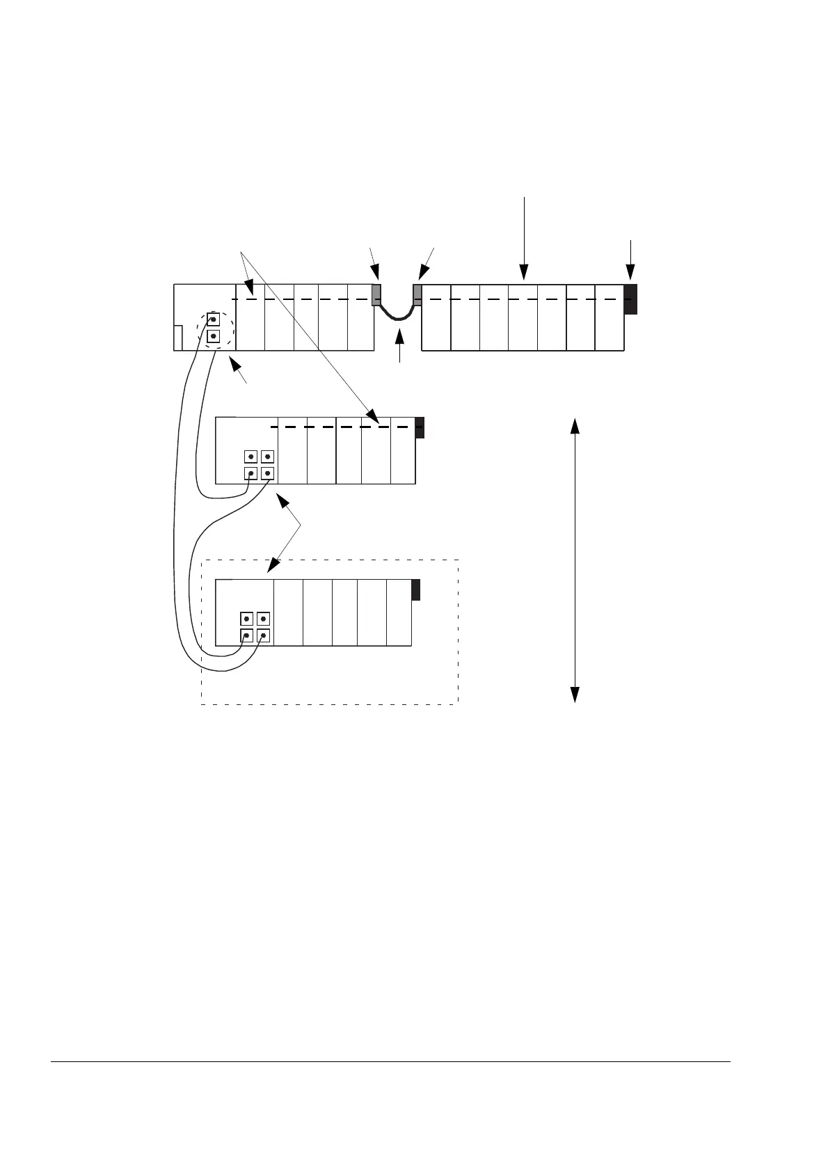
Figure 2-7 An I/O station. The diagram shows I/O devices installed on
both electrical and optical ModuleBus.
12
3 4 5 6 7 8 9101112
12
345
12
345
AC 80
TB81x TK801V00x ModuleBus
Extension Cable Connector
S800 I/O Devices (consisting of Module
TB807 Terminator Latch
X4, X5
X4, X5
Optical
TB820
I/O Cluster
Optical Port Extension Cable
Up to 7
I/O Clusters
ModuleBus
I/O Cluster
TB805 TB806Electrical ModuleBus
Termination Units [MTU] and I/O Modules)
ModuleBus Modem
(max. length 2 m)