123456 789
10 11
12 13
46 47 48 4938 39 40 41 42 43 44 45
14 15 16 17 1819
20 21 22 23 24
25 26 27 28 29 30 31 32 33 34 35 36 37
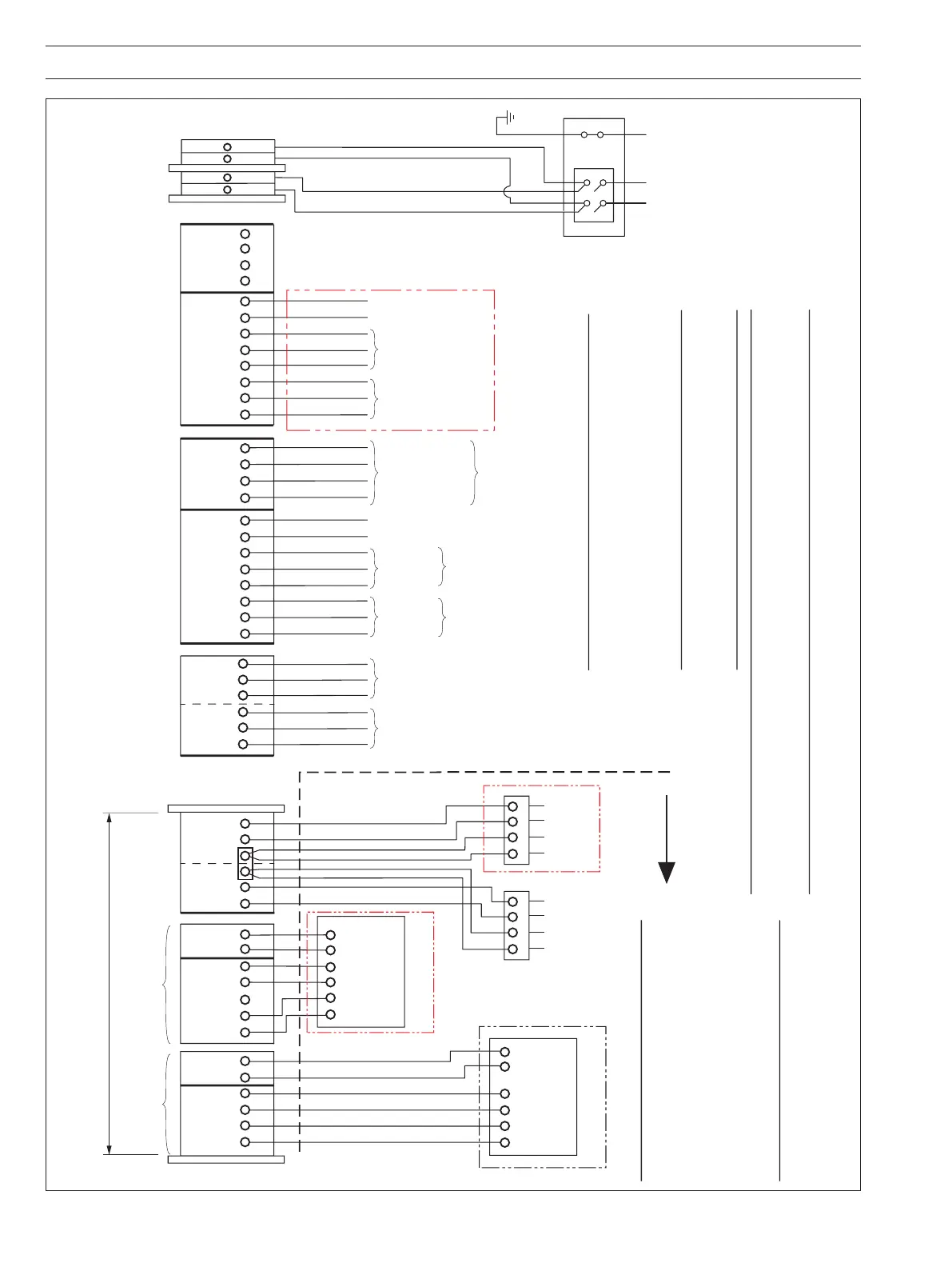
Katharometers
Unit 1
Unit 2Unit 1
Unit 2 Unit 1 Unit 2
TB14/13TB16/15TB18/17
TB12
14 13
From
PSU1
From
PSU2
Blue Terminals
Alarm and
Retransmission 1
TB11
Not applicable
to AK104
Alarm and
Retransmission 2
TB10
N/O
Common
N/C
N/O
Common
N/C
N/O
Common
N/C
Common
Range 3
Range 2
Range 1
Cubicle Terminal Blocks
+
–
+
–
H
2
in Air
Alarm 1
H
2
in Air
Alarm 1
H
2
in Air
Alarm 2
Retransmission
Retransmission
Range Selector
Switch Position
Indicator
23910
14
Katharometer
Panel 1
23910
14
Katharometer
Panel 2
Hazardous Area
Optional
Low Flow
Alarms
Ex ia llC T4
Optional
Low Flow
Alarm Relays
2
3
1
42
3
1
4
Only
AK104
OR
Air in
Purge Gas
Alarm 1
if AK101 **
N/O
Common
N/C
H
2
in Air
Alarm 2
Common
N/C
N/O
Common
N/C
N/O
Relay 1
Relay 2
*
Terminal
Box
Screen
Black
Red
White
Screen
Black
Red
White
Katharometer
H
2
& Air in CO
2
H
2
in Air
Katharometer
H
2
& Air in CO
2
H
2
in Air
++––
++––
*
Note. I.S. Circuits
It is imperative that wiring instructions are followed implicitly.
Earth continuity must be checked for correct bonding.
Warning.
The case-mounted Instrinsically Safe Earth
stud (see Fig. 4.5) must be connected to
the plant High Integrity Earth. The maximum
resistance from this earth stud to the plant
High Integrity Earth must be <0.1
Ω
. This
earth is essential to the correct operation of
the zener safety barrier.
Warning.
The case-mounted System Safety Earth stud (see Fig. 4.5)
must be connected to an earth point ensuring that the
maximum resistance is <1
Ω
. This is to ensure optimum
safety for both the system and personnel/operators.
Note.
Katharometer Panel 1 is connected internally to the Upper Display of the 6553 Display/Control Unit.
Katharometer Panel 2 is connected internally to the Lower Display of the 6553 Display/Control Unit.
*
Note. Not available if single Model AK104 is fitted to the cubicle.
** [There is no second alarm
on TB11 of the AK101}.
*
*
*
L N
L N
Unit Nº 2 Unit Nº 1
TB8 TB7
Mains T/B
*
Isolator Unit
(optional)
1
L
L
N
NLN
E
LN E
2
3
4
Fig. 5.7 Wiring Diagram for Cubicle-Mounted Display Monitor