ControlMaster CM30 and CM50
Universal process controllers,
1
/4 and
1
/2 DIN 4 Installation
12 IM/CM/ED–EN Rev. B
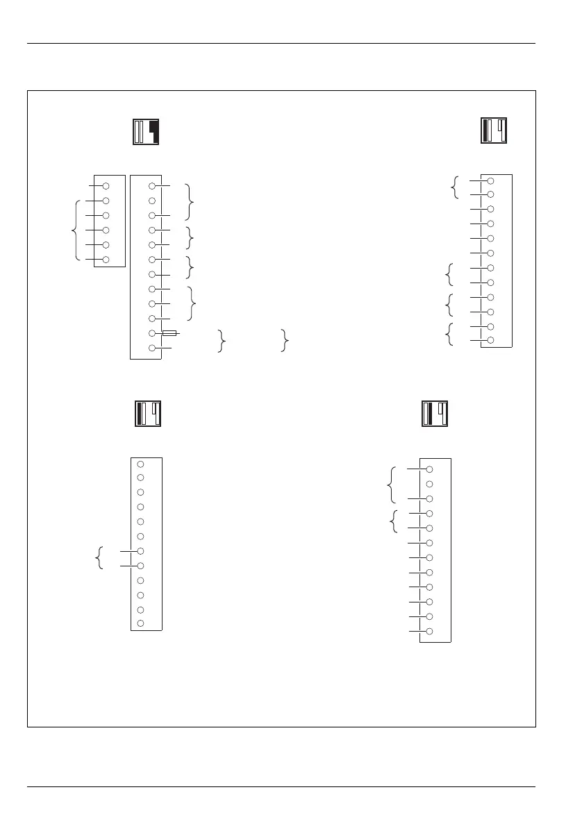
4.5.1 CM30 Electrical Connections
Fig. 4.8 CM30 Electrical Connections
+
29
30
31
32
33
34
35
36
37
38
39
40
+
1
2
3
4
5
6
7
8
9
10
11
12
13
14
15
16
17
18
+
+
+
41
42
43
44
45
46
47
48
49
50
51
52
+
+
41
42
43
44
45
46
47
48
49
50
51
52
Analog
Input 3
Analog
Input 4
Tx PSU
Digital Input / Output 3
Digital Input / Output 5
Digital Input / Output 6
Digital Input / Output –
Comms*
Tx PSU
Analog Input 1
Analog Input 2
Relay Output 1
Line***
100 to
240 V AC
10 W
10 to
36 V DC
Rear View Rear View
Rear View
Option
Board 1
Option
Board 2
Standard
Connections
Digital Output + External
NC
C
NO
Analog / Digital Output 1
Digital Input / Output 4
Digital Output + External
Digital Input / Output 1
Analog Output 2
Digital Input / Output 2
Digital Input / Output –
**
C
**
C
**
C
Relay Output 2
Relay Output 3
Relay Output 4
Neutral
*Refer to rear panel for MODBUS connections
**N/O (factory default) or N/C contact selection made via internal jumper links – see page 9
***200 mA Type T fuse (mains AC) or 2 A Type T fuse (24 V DC) and external isolating switch
Option
Board 1a
Rear View
Relay
Output 2
C
**