Chapter 2 - Start-Up Instructions
IV F
2 - 6 DCS 600 Operating Instructions
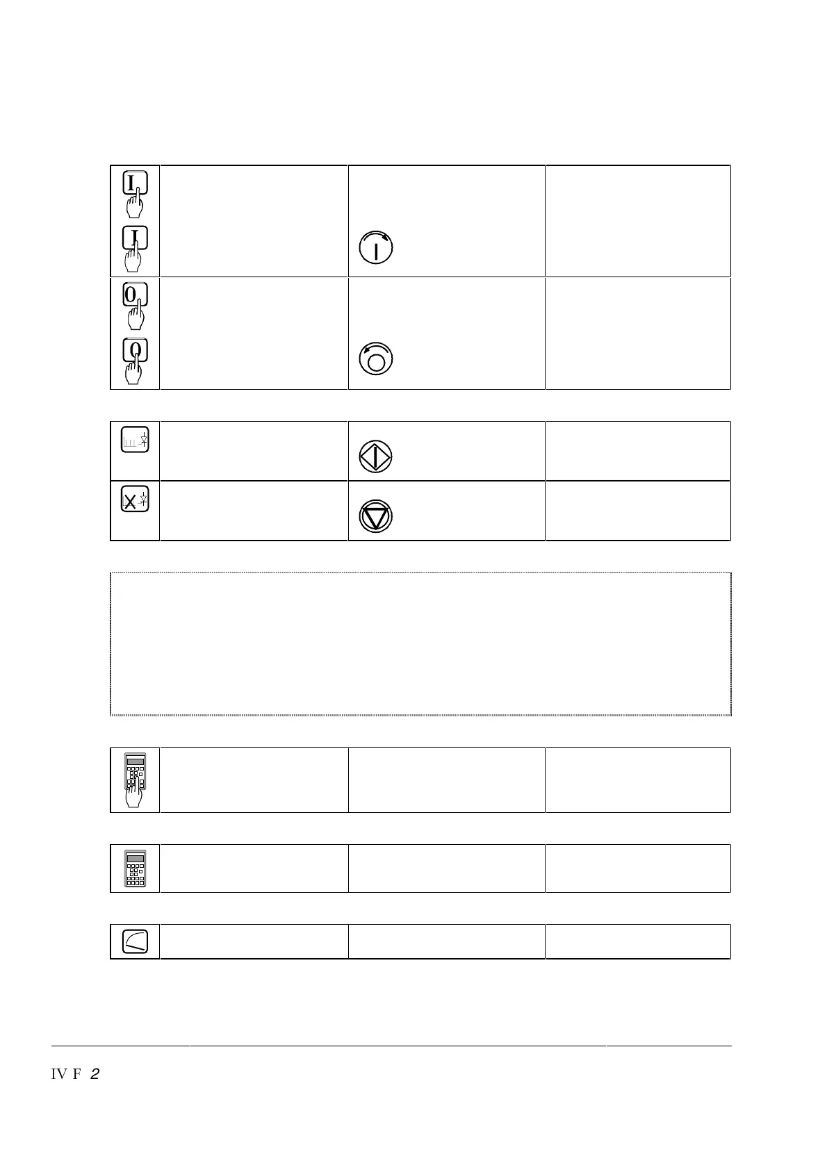
Symbols for switching the electronics or the power section ON and OFF
El
-Switch ON electronics (El)
-Switch ON contactor, i.e.
the unit will be connected
to the supply
(POWER ON)
Control Panel key:
(when in LOCAL mode)
El
-Switch OFF electronics (El)
-Switch OFF contactor, i.e.
the unit will be discon-
nected from the supply
(POWER OFF)
Control Panel key:
(when in LOCAL mode)
Symbols for enabling / disabling the reference
- ENABLE reference, i.e.
START DRIVE
Control Panel key:
(when in LOCAL mode)
- DISABLE reference, i.e.
STOP DRIVE
Control Panel key:
(when in LOCAL mode)
System-dependent planning
During normal operation the control commands like SWITCH ON and SWITCH OFF,
ENABLE etc. will be preset by APC2 or fieldbus adapter. These Operating Instructions
only describe the start-up procedure via panel CDP 312 when in LOCAL mode or/and
via PC program DRIVES WINDOW.
During the start-up procedure a suitable possibility for safe shutdown (switching OFF)
will be required if there is a wrong setting of parameters. In most cases it will not be
sufficient to allow an operation of EMERGENCY STOP (EME-STOP) with a ramp
function!
Symbol for altering parameters
Enter at keyboard (with
Parameter Mode [PAR])
e.g. 15.05 = 3 Assign the value of 3 to
Parameter 15.05
Symbol for displaying parameter values
Display
Symbol for measuring physical variables
Measure