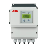
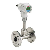
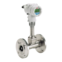
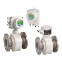
FSM4000 ELECTROMAGNETIC FLOWMETER | DS/FSM4000-EN REV. L
—
… Model SE41F
Flange DN 125 to 400 (6 to 16”), aluminum sensor housing (shell housing)
All specified dimensions and weights are in mm (in) or kg (lb). The specified weights are approximate figures. The maximum
weight is always provided.
Female thread (either ½” NPT or M20 x 1.5), see model coding. In the case of a ½” NPT, there is a plug instead of a PG cable
entry.
Figure 16: Flange DN 125 to 400; sensor housing
Dimensions - flange device, aluminum sensor housing (shell housing)
2 3
4
4
4
125 (5")
-1
6
PN 16
1
311
6
1
150
250
150 (6")
-1 PN 16
1
1
150
200 (8")
-1, PN 10 to 16
1
1
-1, PN 40
1
300
Tolerance L: +0 / −3 mm (+0 / −0.018 in)
 Loading...
