Operation Manual / 4 Product description / A130-H.. - A140-H
8 Dismantling and fitting / 8.18 Installing the gas outlet flange
© Copyright 2020 ABB. All rights reserved. HZTL4030_EN Rev.F February 2020
8.18 Installing the gas outlet flange
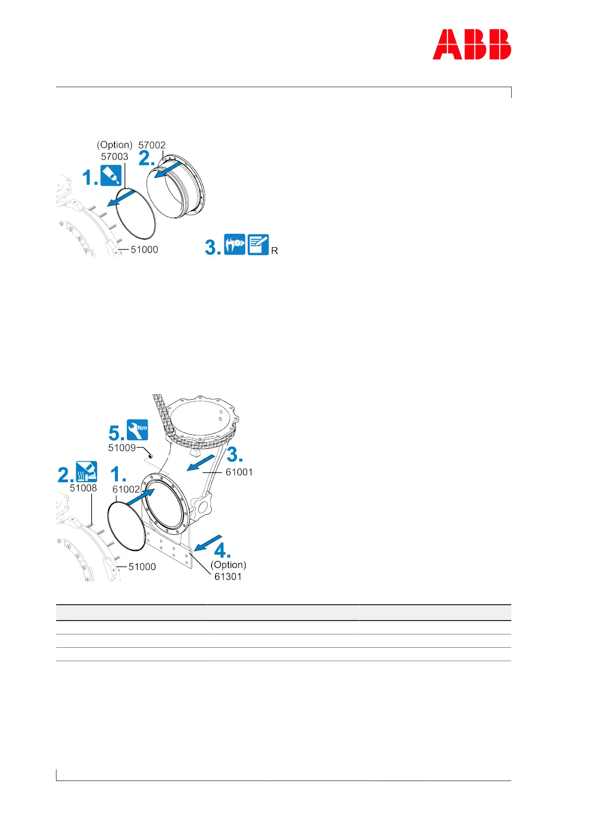
Fig.51: Installing the gas outlet flange
1. If present: Insert the metal C-ring(57003) into the turbine casing(51000) and secure with
high-vacuum grease.
2. Install the gas outlet flange(57002) in the turbine casing.
3. Measure radial clearance(R) (see chapter Radial clearances N and R).
8.19 Installing the gas outlet casing
Fig.52: Installing the gas outlet casing
Product Size Tightening torque [Nm]
A130 M8 20
A135 M10 40
A140 M12 65
Table42: Tightening torque (51009)
1. Insert a new gasket(61002) into the gas outlet casing(61001).
2. Coat the threads of the studs(51008) with high-temperature grease.
3. Attach the lifting gear to the gas outlet casing(61001) and position the gas outlet casing
in the correct position on the turbine casing(51000).
Page 82 / 93
 Loading...