A - 4 WBPEEUI240766B0
Configuring Inputs
Figure A-6 shows the cabling for the IMASI03 module. The
NKAS01 (or NKAS11) cable connects the termination unit to
the IMASI03. The NKAS01 cable has PVC insulation and is
rated for 80° C (0 to 176° F) at 300 V (UL rated type CL2). The
NKAS11 cable has non-PVC insulation and is rated for 90° C
(0 to 194° F) at 300 V (UL rated type PLTC).
NOTE: The example in Figure A-4 is an NTAI06 termination unit with revision B
hardware.
Current 4 to 20 mA, external or system powered
3-wire RTD Resistance range: 0 to 500 !
RTDs: 10, 100, 120 !
Chinese 53 ! (3-wire)
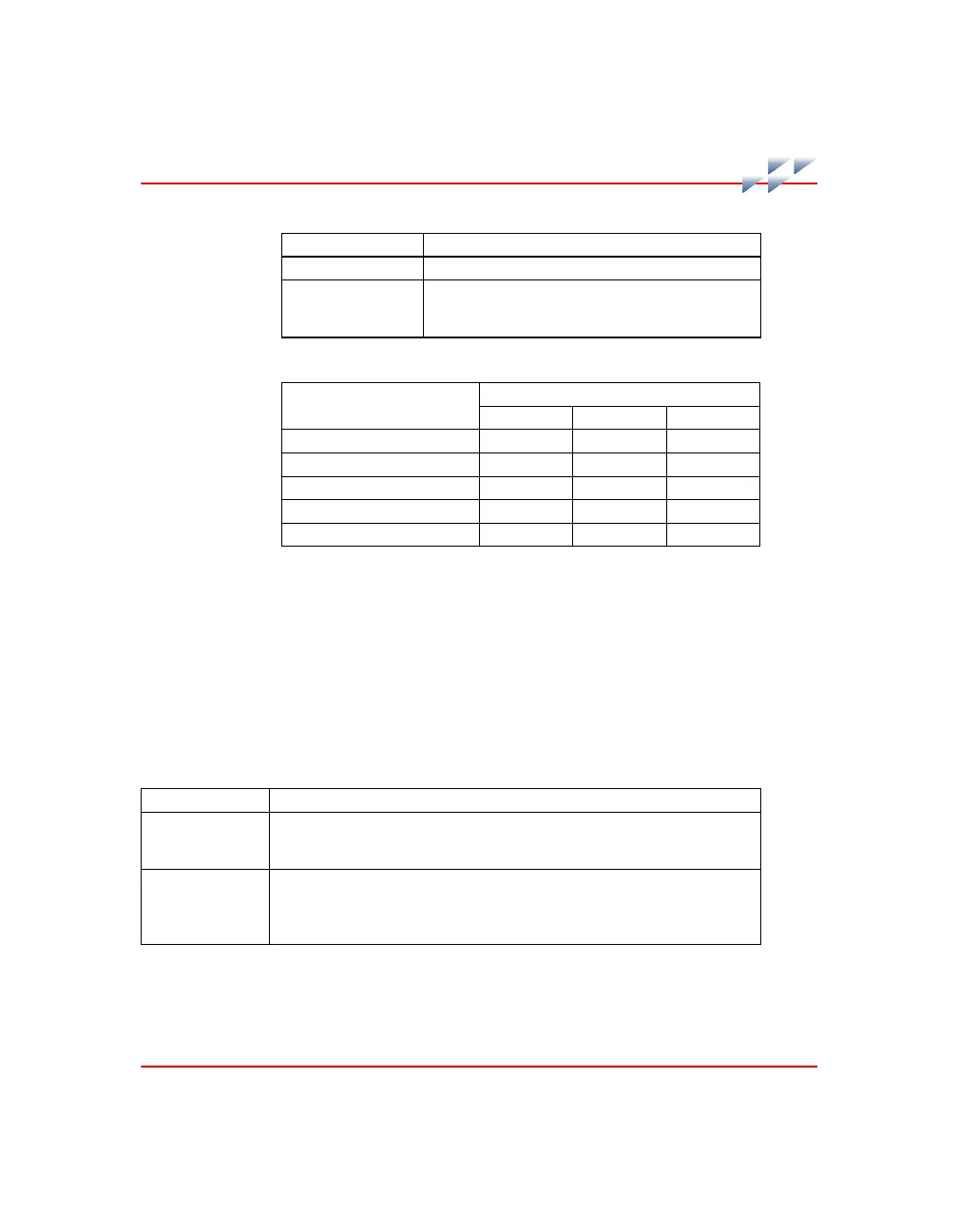
Tabl e A-2. N TAI06 Ju mper Co nfigu rations
Input Type
Jumper Number
J1 - J32 J33 - J48 J49 - J64
Single-ended voltage 1 - 2 1 - 2 2 - 3
Differential voltage 1 - 2 1 - 2 1 - 2
System powered 4 to 20 mA 2 - 3 2 - 3 2 - 3
External powered 4 to 20 mA 1 - 2 2 - 3 1 - 2
3-wire RTD 1 - 2 1 - 2 1 - 2
NOTE: Jumpers used by each input channel are listed with the terminal assignments in Figure A-3.
Tabl e A-1. N TAI06 In put Type s (continued)
Input Type Signal Type
Tabl e A-3. N TAI06 In put Type Desc riptions
Input Type Input Description
Single-ended
voltage
This jumper configuration connects the minus (-) input terminal to I/O COM on
the NTAI06. The IMASI13 measures the voltage at the plus (+) input terminal
with respect to the C terminal. No connection to the C terminal is necessary.
Differential voltage This jumper configuration connects the plus (+) and minus (-) inputs directly to
IMASI13 differential input. Channel to channel and channel to system signal
isolation is achieved for all voltage input types, including high level voltage,
millivolts and thermocouples. No connection to the C terminal is necessary.