Setup and Installation
WBPEEUI240766B0 3 - 3
6. Verify there is sufficient logic and field power for the mod-
ules in the module mounting unit.
Address Selection Switch (S1)
The ASI module must have an address to communicate with
the controller. The ASI module can have any one of 64
addresses (address 0 to 63) on the I/O expander bus. This
address identifies the ASI module to the controller and must
be the same as the address set in the controller configuration
data (FCs 215 and 216, specification S1).
Set the address with the eight position address dipswitch S1
(Fig. 3-1). The six right switch positions (three through eight)
of S1 set the six-bit address. Positions one and two must
remain closed (set to zero) for normal operation (Fig. 3-2).
The address is set in binary format. Table 3-1 shows some
example address settings for switch S1. Refer to Section 6 for
the diagnostic settings. Record the I/O expander bus address
of the ASI module in the space provided.
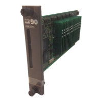
Figure 3-1. Module Layout
P1
P3
P2
MODULE STATUS
LEDS
S1 ADDRESS
SWITCH
EDGE
CONNECTORS
ANALOG INPUT
CONFIGURATION JUMPER
BLOCKS, J1-J16
IMASI13
S1U29
J1 J2 J3 J4 J5 J6 J7 J8 J9 J10 J11 J12 J13 J14 J15
J16
T01063B