Do you have a question about the ABB IMASI13 and is the answer not in the manual?
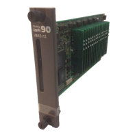
Describes the IMASI13 Analog Input Module, its function, and system compatibility.
Outlines the qualifications and experience required for personnel handling the module.
Highlights the module's flexibility in creating process management systems and its input signal capabilities.
Lists the sections covered in the instruction manual for clarity.
Provides guidance on reading the manual sequentially or referring to specific sections as needed.
Explains symbols and abbreviations used in the manual for consistent understanding.
Defines terms and abbreviations specific to ABB Automation or used differently.
Lists ABB Automation instructions referenced in this document for further information.
Lists nomenclature related to the IMASI13 module for reference.
Details handling precautions for devices sensitive to electrostatic discharge.
Covers equipment environment and electrical shock hazards during maintenance.
Provides detailed warnings regarding power disconnection and potential electrical hazards.
Details the operating voltage and current for the module.
Lists the types of analog inputs supported and their configurations.
Specifies the accuracy of measurements for different input types.
Details the module's compliance with EMC standards and test results.
Specifies ambient temperature, humidity, altitude, and air quality requirements.
Lists directives and standards the product complies with for CE marking.
Details certifications obtained or pending for the product.
Explains inputs, logic, communication, and connections for the IMASI13 module.
Describes the physical layout, connectors, and basic configuration elements of the ASI module.
Explains how the ASI module functions as an intelligent module with an onboard microcontroller.
Details the analog-to-digital converter per channel and isolation methods used.
Explains how the module measures cold junction RTDs for thermocouple compensation.
Covers the dipswitch for setting the I/O module address and diagnostics.
Explains the function and status indications of the module's red and green LEDs.
Describes the high-speed bus for controller-module communication.
Describes the function of the NTAI06 termination unit for field signal connection.
Explains how function codes (FCs 215, 216, 217) configure and calibrate the ASI module.
Details how the A/D converter samples input signals continuously.
Explains how cold junction compensation is applied to thermocouple inputs.
Details how users can apply linear adjustments for gain and offset.
Explains how input signals are converted to engineering units like degrees C or F.
Lists built-in tests performed when the module is in diagnostic mode.
Details how module specifications can be changed during online configuration.
Describes how modules and termination units mount in ABB Automation enclosures.
Explains procedures before module operation and configuration.
Provides critical precautions for handling static-sensitive devices.
Details steps for examining hardware for transit damage and proper storage.
Lists checks to perform before applying power to the ASI module.
Explains how to set the module's address using the eight-position dipswitch.
Details setting specifications and input jumpers for module configuration.
Explains the process of connecting cables for module operation.
Guides on physically installing the module into the MMU.
Details connecting the IMASI13 module to the NTAI06 termination unit via specific cables.
Explains configuration and field calibration for IMASI13 module inputs.
Explains the role of FCs 215, 216, and 217 in configuring the module.
Describes factory calibration data storage and optional field calibration procedures.
Explains field calibration procedures, including restoring factory data and tuning gain/offset.
Provides detailed steps for calibrating individual channels for various input types.
Explains the startup and operation of the IMASI13 module.
Describes the initial communication and configuration process upon startup.
Explains how the controller interacts with the ASI module for data processing.
Describes the function of the module's red and green status LEDs.
Explains error signs and corrective actions for the IMASI13 module.
Lists problem reports generated by FCs 215 and 216 and their types.
Details how module errors are reported via FC 215 and FC 216 status bytes.
Provides an example of troubleshooting configuration errors related to addresses.
Shows pin connections for the IMASI13 module's P1, P2, and P3 connectors.
Emphasizes the importance of preventive maintenance for equipment reliability.
Lists preventive maintenance tasks grouped by maintenance interval.
Lists tools and equipment necessary for performing maintenance procedures.
Covers cleaning and checking connections as detailed in the schedule.
Guides on verifying the integrity of signal, power, and ground connections.
Explains the replacement steps for an IMASI13 module.
Details the procedure for replacing a faulty ASI module with a new one.
Introduces the NTAI06 unit and its configuration for analog inputs.
Explains the role of RTDs in the termination unit for thermocouple compensation.
Describes how jumpers on the termination unit configure analog inputs.
Highlights differences between IMASI03 and IMASI13 for direct replacement.
Details required changes to function code 216 for replacement.
Compares power consumption between IMASI03 and IMASI13 modules.
| ABB Type Designation | IMASI13 |
|---|---|
| Extended Product Type | IMASI13 |
| Rated Voltage | 24 V DC |
| Protection Class | IP20 |
| Product Name | Analog Input Module |