WBPEEUI240766B0 5 - 1
Section 5
Operating Procedures
Introduction
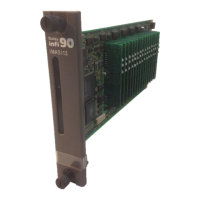
This section explains the startup and operation of the IMASI13
module (ASI).
Startup
Communication between the ASI module and controller starts
when the two modules are configured correctly (refer to
Section 4). The ASI module address in FCs 215 and 216 must
be the same as the address set on the address dipswitch.
Upon startup, when power is applied to the ASI module and
the controller is put into execute mode, all channels are ini-
tially marked bad quality until the controller downloads the
configuration data and the ASI module processes a valid input
signal.
Operation
The controller sends an interrupt command to the ASI module
whenever it sends new configuration data. This interrupt
causes the ASI module to read the configuration data and ini-
tialize its input handling, conversion, and compensation calcu-
lations. Once configured by the controller, the ASI module
scans its inputs and makes corrected values available to the
controller over the I/O expander bus. The controller reads the
values from the ASI module during its normal segment cycle
operations. Refer to Section 2 for more information about ASI
module theory of operation.
Status LEDs
The IMASI13 module has two LEDs, one red and one green
LED indicator, that show its operating status.
• Red flashes on power-up.