4 - 2 WBPEEUI240766B0
Configuring Function Codes
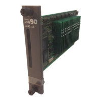
function codes specify the I/O expander bus address of the
IMASI13 module as well as the channel number on the analog
input module connected to an analog input signal. The type of
the input, as well as the zero and span in engineering units,
must also be specified to insure proper scaling and corrections
for field calibration or cold junction compensation. Function
code specifications also contain the A/D resolution, lead wire
resistance (if such a correction is desired), and primary fre-
quency of the noise to be rejected by each input.
For cold junction compensation, the block which represents
the cold junction input must also be specified. To use the ana-
log input module’s onboard cold junction reference, set specifi-
cation S3 in FC 215 to the block address of FC 215.
Any channel can be used as a remote cold junction reference.
In FC 216, specification S4, enter:
1xx
The xx, which ranges from 01 to 99, specifies the input signal
type.
When an input channel is selected as a remote cold junction
reference, software smoothing of the input reading takes place.
This smoothing allows the temperature response of the remote
cold junction reference to closely match the temperature
response of the remote terminal blocks.
Each ASI module configured for a thermocouple input requires
a cold junction reference. Each ASI module can only have one
cold junction reference for up to 16 thermocouple inputs. The
exception to this is when one of the thermocouple inputs is
used as a remote cold junction reference.
NOTE: All specifications in FCs 215, 216, and 217 associated with the
IMASI13 can be changed during online configuration. When changes are made
to the input channel parameters (FC 216), the channel will hold the last value
with status unchanged for a short period. This hold time is based on the num-
ber of channels that were changed during online configuration, as well as the
resolution specified in the FC 216 blocks for that channel. Plan on a hold time
of four seconds (worst case) for each FC 216 changed during online configura-
tion.
Define one FC 217 in the controller configuration in case ASI
module tuning or field calibration operations are needed later.