PGC5000
PGC5000 Series Service Instructions 6 Component repair
SI/PGC5000-EN, rev B 41
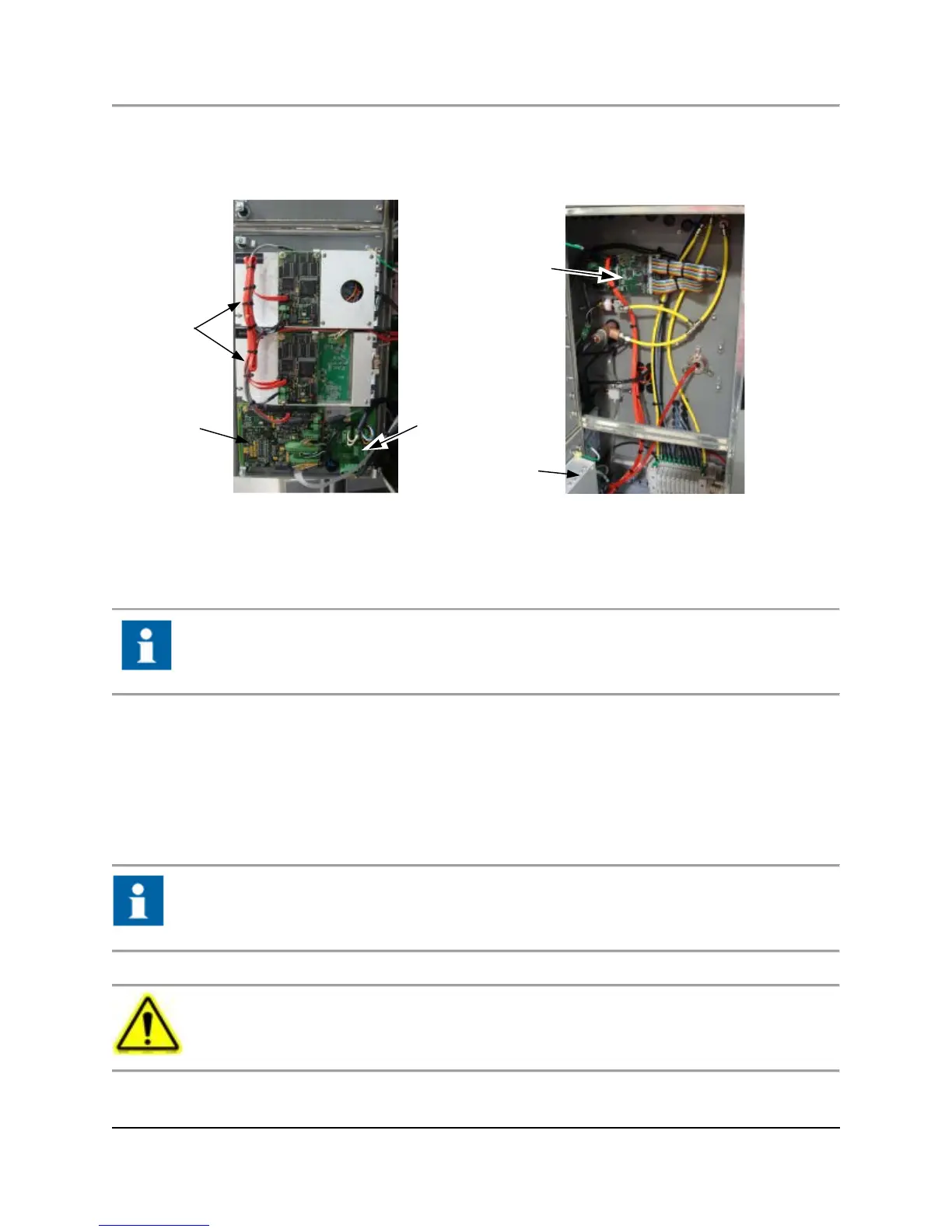
6.4.3 Class C oven component locations
The Class C Oven incorporates PCBs mounted on the inside of the front and side doors and on walls of the electronics
compartment (see Figure 6.6). Before removing any boards ensure power is off and cable routing is noted. Some boards may
require address and termination changes.
Fig. 6.6. Class C Oven Component Locations
6.5 Replacing the EPC control pcb
In the Class B Oven, the EPC Control PCB is attached to inside of electronics compartment door (left side of oven). In the Class C
Oven, it is attached to inside of upper electronics compartment door (left side of oven).
Always note routing and marking of cables (pin 1 location, etc.). Note jumpers and move to replacement
board as necessary.
1. Remove cables using proper tools.
2. Undo hex head screws and remove board.
3. Attach updated or new board to door, starting with the center top screw. (Do not tighten).
4. Adjust board, aligning all outer screw holes with mounts.
5. Tighten all screws.
6. Attach cables.
7. Test.
6.6 Repairing the epc control assembly
To ensure integrity of the components within the EPC, use the tools in EP Service Took Kit 801K005-1
when disassembling or assembling the EPC Control Assembly.
6.6.1 Preparation
Before performing EPC repair, you must turn off power to the analyzer as described in the following
steps.