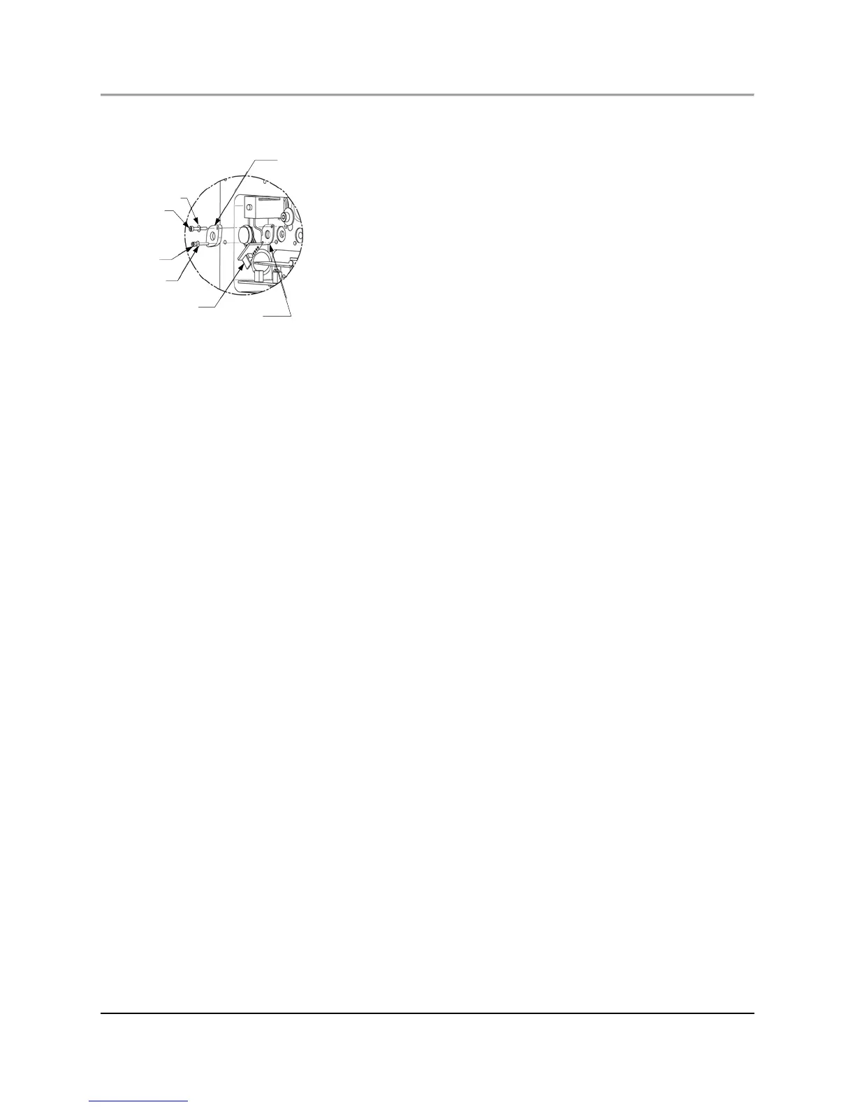
Fig. 6.10. Installing the New Sensor PCB
1. Place a Belleville washer on each mounting screw, with the rounded side toward the screw.
2. Place the screws through the holes in the mounting plate.
3. Place the gasket on the end of the two screws, with enough screw thread showing through the gasket to start the screws
into the hole.
4. Insert the screws into the hole in the block, just far enough to hold them in place.
5. Place the Sensor PCB into position between the plate and the gasket, with the cable at the bottom right edge.
6. Slightly tighten the two screws evenly, removing any play in the assembly (but applying no torque) and ensuring it is
mounted straight up and down.
7. Tighten one screw, using torque limiting screwdriver ABB Tool 801Z003-1, set at 1 in.-oz.
8. Tighten the second screw to 2 in.-oz.
9. Retighten the first screw to 3 in.-oz.
10. Retighten the second screw to 4 in.-oz.
11. Retighten the first screw to 5 in.-oz.
12. Retighten the second screw to 6 in.-oz.
13. Retighten the first screw to 7 in.-oz.
14. Retighten the second screw to 7 in.-oz.
15. Plug the Sensor PCB cable into the corresponding connector on the Control PCB.
16. If another Sensor PCB Assembly needs to be replaced, repeat the appropriate steps to remove the old Sensor PCB
Assembly and install a new one. Be careful to observe the precautions stated in the Note at the beginning of this
procedure.
17. Reconnect the large ribbon cable to the Control PCB.
18. Ensure that the flame-proof or explosion-proof surfaces of the cover or the body of the Control Assembly are not
damaged.
19. Reinstall the EPC Control Assembly cover and insert the ten screws and tighten them to 16 in.-lb, using ABB Tool
TL1000/TL1002.
20. Reinstall the EPC cover panel and insert the four screws.
6.6.6 Removing a proportional valve
1. Perform the “Preparation” procedure.
2. Remove the four screws holding the top panel on the front of the oven.
2. Remove the ten screws holding the EPC Control Assembly cover and retain the screws for later use.
4. Unplug the large ribbon cable from the Control PCB and fold it back to your left and out of the way.
5. Locate the valve to be replaced (See Figure 6.8).
6. Disconnect the valve cable at the connector on the Control PCB.