PGC5000
PGC5000 Series Service Instructions 5 Diagnostics and troubleshooting
SI/PGC5000-EN, Rev B 17
these LEDs blink green; they may appear solid during heavy traffic. If a CAN communication error is detected, an LED will turn
red.
CR2 CAN A transmit
CR4 CAN A receive
CR6 CAN B transmit
CR8 CAN B receive
CR11 CAN C transmit
CR13 CAN C receive
On the unpopulated side of the Oven Controller PCB), CR9 is a small green LED which when lit, means the OC is in a hold state.
The OC PCB comes up in this state. Once the Master Controller initializes the DPM between the two, the Master Controller will
release the OC PCB, at which time CR9 will go off.
5.3.3 DTC digital pcb, version 1
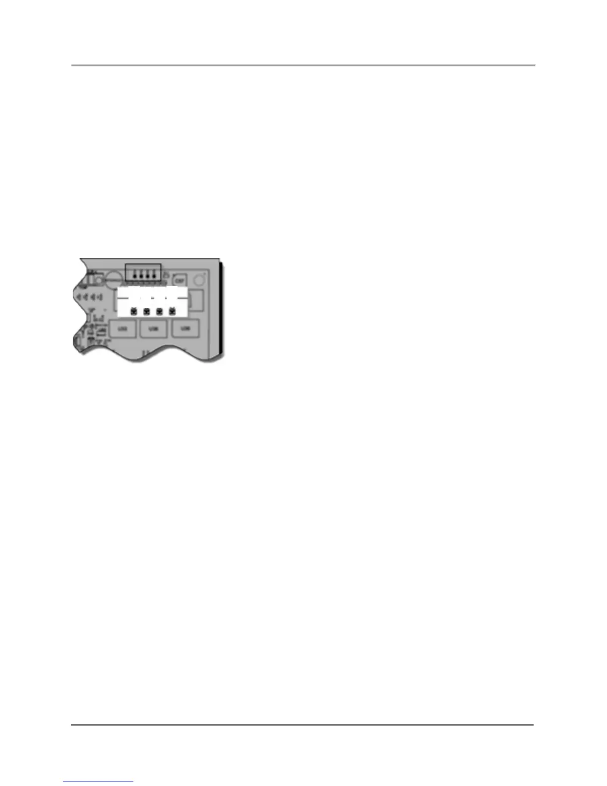
The DTC digital board has four LEDs (CR1 to CR4) on the upper edge, beside the solenoid cable connector, as shown in Figure
5.7. They are numbered from left to right.
Fig. 5.7. Location of DTC Digital Board LEDs
Their normal operation indications are:
CR1: Green, blinking more on than off once per second (heartbeat.)
Amber, blinking. The bootloader operation is executing.
CR2: Green, blinking, rapid rate (noticeably faster than CR1); indicates method executing and Real Time Clock
signal present.
Amber, blinking, slow rate. No method executing and an RTC signal is present.
CR3: Green, solid: AC power present at the DTC analog board.
Red, solid: no power detected. Example: A T-rating error will shut down control and disable power resulting
in a red LED.
CR4: Off during normal operation.
On the Power-up Cycle, the four LEDs indicate the processes attempted if the DSP fails (none are blinking):
CR1 CR2 CR3 CR4
off red off off CAN initialization error
off amber off off application initialization error
red red off off CAN node/network setup error
green red off off no other node on CAN bus
amber red green off programming failed during last power-up
amber amber green off watchdog timeout during last power-up
red off green off power-up state chip inaccessible
red amber green off invalid power-up state
red amber off off reload in progress
off off green off start hardware setup
off green off off bootloader CAN setup
off off amber off DSP initialization
red amber red off EEPROM access error
off off red off bootloader initialization
off amber amber off CANopen setup