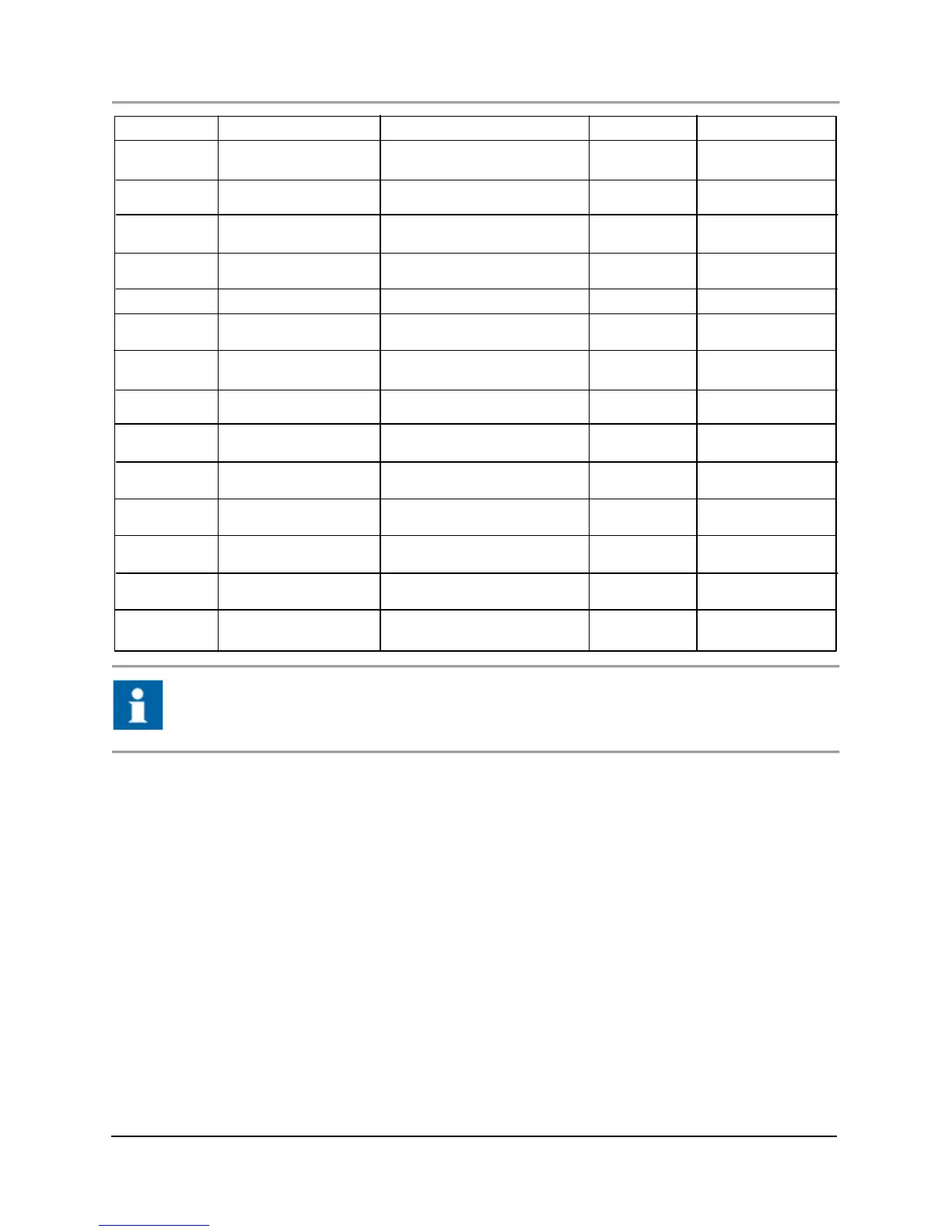
INDICATOR ISSUE RESOLUTION (CHE CK & CORRECT) RESET SOURCE
Vo l Fl ow Hi gh Volumetric Flow e xceeds Inf orma ti on Only. AOC Fast Lo op
High Limit
Vo l Fl ow Hi gh Hi gh Volumetric Flow exceeds Inf or ma ti on Only. AOC FastLoop
High High Limit
Pressure Low Low P ressure low er t han L ow Inf orma tion Only. AOC Fast Loop
Low Limit
Pressure Low P ressure lo wer t han L ow Inf orma tion Ony. AOC Fast Lo op
Limit
Pressure High Pressure exceeds High Limit Inf orma tion Only. AOC FastLoop
Pressure High High Pressure exceeds High Inf orma tion Only. AOC FastLoop
High High Limit
Te mp L ow L ow Temperature lower than Inf orma tion Only. AOC Fast Loop
Low Low Limit
Te mp L ow Temperature lower than I nf orma tion Only. AOC Fast Loop
Low Limit
Te mp High Temperature e xceeds High Inf or ma ti on Only. AOC FstLoop
Limit
Temp High High Temperature exceeds High Inf orma ti on Only. AOC Fast Lo op
High High Limit
Loo p DP Low L ow Loop Di ffe re nt ial Pre ssu re Inf orma ti on Only. AOC Fast Lo op
lower than Low Low Limit
Loop DP Low Lo op Di ffe re nt ial Pre ssure I nf orma tion Only. AOC Fast Loop
lower than Low Li mit
Loop DP High Loop Di ffe re nt ial P re ssure Inf or ma ti on Only. AOC FastLoop
exceeds High Limit
Loop DP High High Loop Di ffe re nt ial Pre ssure Inf orma ti on Only. AOC Fast Lo op
exceeds High High Limit
“#” is used in place of numbers to eliminate repeats in multiple card and oven systems. "Information
Only" signifies the set indicator is activated in response to the setup criteria. It does not necessarily
identify a fault.
5.6 Operation troubleshooting
This subsection provides troubleshooting information by category. Included in this information are symptoms, causes, and
suggestions for further fault isolation.
5.6.1 Baseline noise
The baseline (detector signal) with no sample injection appears as noise similar in appearance to “grass” on a two dimensional
drawing in the graphics display. The baseline is observed on the Manual Mode tab of the Master Controller.
Cause: Baseline or detector noise can result from contaminated carrier, makeup gas, tubing or regulators. This type of
contamination is much less pronounced with a TCD than for an FID. Other causes include defective filaments (TCD), detector
wiring, or electrical noise in the detector electronics or power supplies.
Check the background level by going to the Setup Tab>FID button and with the flame lit manually, AUTO ZERO the baseline.
(The AUTO ZERO OFFSET for an FID should be > 10 mv.)
5.6.2 Baseline or signal offset
The baseline (detector signal) is continually offset to the positive or the negative with no short term drift up or down scale.
Causes:
1. Incorrect temperatures. Inspect temperature settings and correct if necessary.