Do you have a question about the ABB PGS100 and is the answer not in the manual?
Provides an overview of safety aspects to be observed for the device operation.
Details prohibited uses of the device, such as using it as a climbing aid or support.
Specifies the maximum working pressure, ambient temperature, and process temperature.
Explains that misuse or unauthorized alterations void the manufacturer's warranty.
Highlights danger warnings and the need to avoid risks to health or life.
Defines operator responsibilities for checking material compatibility and national regulations.
States that installation and maintenance must be performed by trained specialist personnel.
Provides instructions for packaging and shipping devices for repair or recalibration.
Promotes environmental awareness and environmentally friendly use of natural resources.
Information on the disposal of electrical and electronic equipment according to WEEE Directive.
Provides guidance on checking for transport damage and storing the transmitter.
Specifies that electrical connections must be made by authorized personnel per diagrams.
Warns about risks when the housing is open and emphasizes depressurizing before work.
Operator responsibility to ensure a secure connection; ABB not liable for breaches.
General disclaimer regarding product functionality and network interface security.
Notes that the HART protocol is unsecured and requires assessment for suitability.
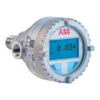
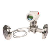
Identifies key components of the gauge/absolute pressure transmitter.
Defines terminology like URL, LRL, URV, LRV, and SPAN for transmitter calibration.
Details the information found on the transmitter's identification and certification plates.
Describes the optional laser-printed stainless steel plate with custom text.
Emphasizes studying instructions and checking device suitability for the measuring point.
Provides guidance on handling and storing the instrument without special precautions.
Explains IP ratings (IP67/IP68/IP69K) and NEMA 4X for housing protection.
Discusses factory configuration considerations like TAG number and calibrated span.
Details certifications required for hazardous area installation (ATEX, IECEx, CSA).
Information on PED compliance for devices with PS >200 bar and PS ≤ 200 bar.
Provides guidance on mounting the transmitter vertically to prevent zero shifts.
Details sealing methods for G ½ B spigot and NPT threaded connections.
Advises using tight cable glands and routing cables downward to prevent moisture entry.
Provides guidelines for correctly laying measuring pipes to avoid deposits and ensure proper function.
Specifies wiring gauge, shielding, voltage range, and capacitance/resistance formula.
Details the electrical connection port, entry types, and recommended stripping length for cables.
Step-by-step instructions for wiring the transmitter, including housing cover removal and connections.
Explains housing grounding requirements and the most effective method for case grounding.
Illustrates the connection scheme for HART communication, including handheld communicator setup.
Details how to set up HART communication using a PC or laptop and the required resistance.
Outlines checks before powering up and steps for putting the transmitter into operation.
Describes the analog output current (4-20mA) and its limits under overload or alarm conditions.
Explains how to set zero/span and manage write protection using the push button.
Details the LCD display's capabilities, including visualization modes and variable IDs.
Describes how to correct zero position shifts due to mounting and calibrate LRV/URV.
Provides instructions and precautions for installing and removing the LCD display unit.
Explains the function of the ventilation port and the importance of keeping it clear.
Explains how to navigate menus and perform Zero/Span adjustments via the LCD display.
Describes how to access the diagnostic menu to view device status and error messages.
Details the structure of the Easy Setup menu for configuration and parameterization.
Illustrates the step-by-step flow for configuring language, tag, units, range, and other settings.
Explains how error/fault messages are displayed on the LCD, including icons and error codes.
Lists error codes, descriptions, possible causes, suggested actions, and transmitter responses.
Continues the list of error codes, descriptions, possible causes, and suggested actions.
Lists further error codes related to electronics temperature, memory, and power supply.
Explains the DAD QR Code option for retrieving device status and troubleshooting information.
Describes the QR Code option for providing channel partner contact information.
States no maintenance is required under normal conditions, but checks are recommended.
Provides instructions for returning defective transmitters and warnings about disassembly.
Details specific conditions for SIL2 version and installation in Group III Db areas.
Guidance on explosion protection in accordance with ATEX directive and national regulations.
States that EU declaration of conformity and type examination certificates are available online.
Explains intrinsic safety requirements for signal circuits and housing opening.
Provides installation requirements for areas with combustible dust, including cable glands and temperature.
Details ATEX and IECEx protection types, permissible temperatures, and power supply limits.
Specifies conditions for SIL2 version relating to dielectric strength tests and installation in Group III Db.
Details HART communication markings, permissible temperatures, and power supply for US CSA.
Details HART communication markings and degree of protection for Canadian CSA.
| Protection Rating | IP65 |
|---|---|
| Output Signal | 4-20 mA |
| Operating Temperature | -20°C to +50 °C |
| Material | Stainless steel |
| Number of streams | 1 |
| Communication | HART |