FEP630, FEH630 ELECTROMAGNETIC FLOWMETER | OI/FEP630/FEH630-EN REV. D 11
Measuring principle
Measurements performed by the electromagnetic flowmeter are
based on Faraday’s law of induction. A voltage is generated in a
conductor when it moves through a magnetic field.
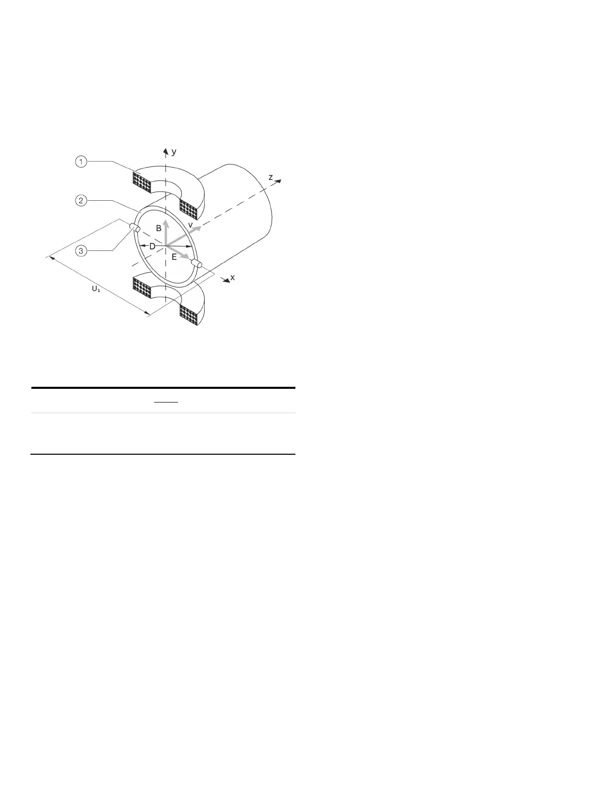
1 Magnet coil
2 Measuring tube in electrode plane
3 Measuring electrode
Figure 4: Electromagnetic flowmeter diagram
vDBU
~
1
v
D
qv
4
2
qvU
~
1
U
1
Measuring span
B Magnetic induction
D Electrode spacing
v Average flow velocity
qv Volume flow rate
With the device-relevant application of this measuring principle,
a conductive measuring medium flows through a tube in which a
magnetic field is generated perpendicular to the flow direction
(see Figure 4).
The voltage induced in the measuring medium is tapped by two
diametrically opposed electrodes. This measurement voltage is
proportional to the magnetic induction, the electrode spacing
and the average medium velocity v.
Taking into account that the magnetic induction and the
electrode spacing are constant values results in a proportion
between the measurement voltage U
1
and the average medium
velocity.
From the calculation of the volume flow rate follows that the
measurement voltage is linear and proportional to the volume
flow rate
The induced voltage is converted by the transmitter to
standardized, analog and digital signals.