114 Product manual - PVS-175-TL;A.1 Version
EN
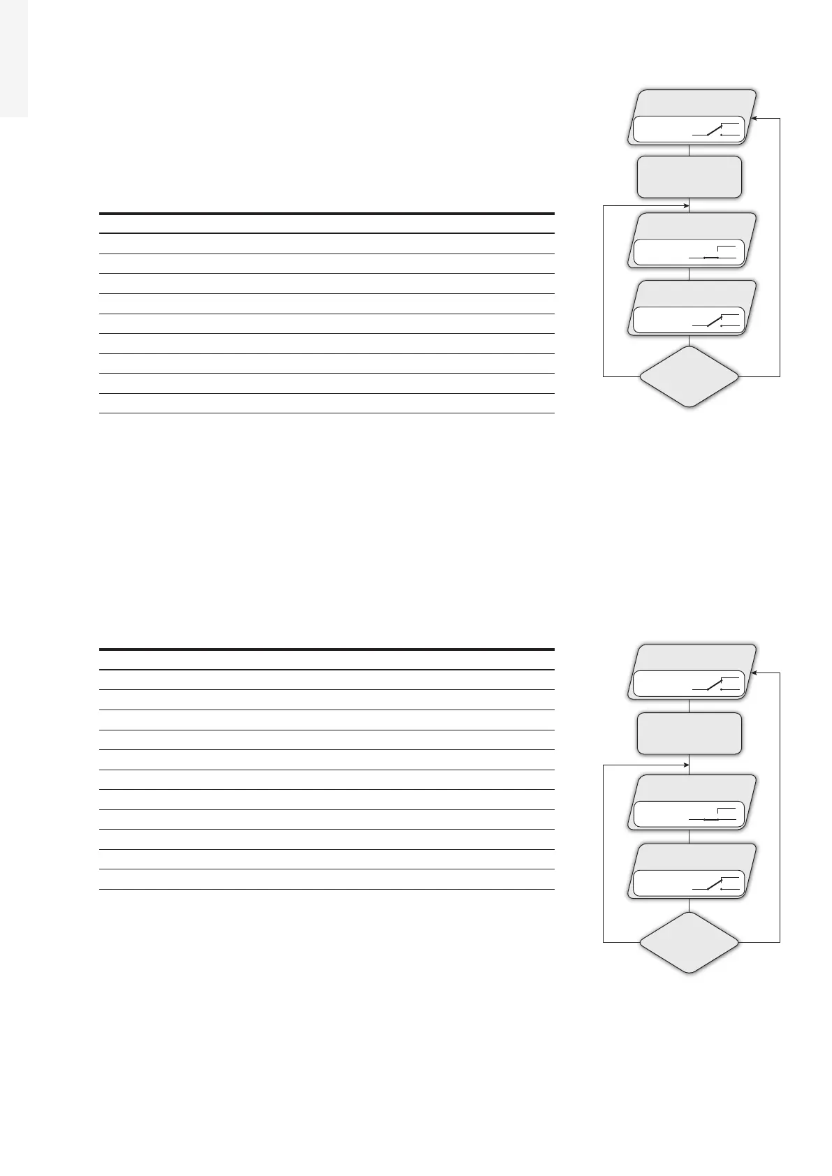
• Alarm ALL - no-latch
The relay is activated (status: switched) whenever an error (code Exxx) or
warnings related to grid parameters out of range (Warning – codes W003,
W004, W005, W006, W007) are present on the inverter. The alarm contact
returns to its resting position when the alarm signal ends, i.e. before the
inverter checks the grid parameters after the alarm state. This is because
grid control state is not an alarm state but a state of normal operation.
Alarms for which the relay is activated
E001 E002 E003 E004 E005 E006
E007 E009 E010 E011 E012 E013
E014 E015 E016 E017 E018 E019
E020 E021 E022 E023 E024 E025
E026 E027 E028 E029 E030 E031
E032 E033 E034 E035 E036 E037
E046 E050 E053 E054 E055 E056
E057 E058 E077 E078 E081 E084
E089 W003 W004 W005 W006 W007
In the presence of W003, W004, W005, W006, W007 signalling, the alarm contact switches and then reset
itself at the end of the alarm signal. This means that during the absence of grid voltage (display message
“Missing Grid”) the alarm contact remains in its resting position.
• Alarm Configurable - no-latch
The relay is activated (status: switched) whenever an error (code Exxx) or a warning (code Wxxx) is
among those selected from the list in the dedicated submenu Alarm Config. The contact returns to its
resting position when the alarm signal ends, i.e. before the inverter checks the grid after the alarm state.
This is because grid control state is not an alarm state but a state of normal operation.
Selectable alarms for which the relay is activated
E001 E002 E003 E004 E005 E006
E007 E009 E010 E011 E012 E013
E014 E015 E016 E017 E018 E019
E020 E021 E022 E023 E024 E025
E026 E027 E028 E029 E030 E031
E032 E033 E034 E035 E036 E037
E046 E050 E053 E054 E055 E056
E057 E058 E077 E078 E081 E084
E089 W001 W002 W003 W004 W005
W006 W007 W009 W011 W015 W046
W047 W048 W051 W058 W059
For the configurable relay operating mode “Alarm Conf.”, the following
considerations are valid:
• If the alarm condition is persistent, the alarm contact cyclically switches
from its resting state to its activated state.
•
In the presence of W002 signalling (Input UV – input voltage below the limit of operation), the alarm
contact switches to then reset itself at the end of the alarm signal. This means that during the reduced
input voltage (display message “Waiting Sun”) the alarm contact remains in its resting position.
•
In the presence of W003, W004, W005, W006, W007 signalling, the alarm contact switches and then reset
itself at the end of the alarm signal. This means that during the absence of grid voltage (display message
“Missing Grid”) the alarm contact remains in its resting position.
INVERTER RUN
ERROR OCCURENCY
ERROR MESSAGE
t=15s
GRID RECONNECTION
t=based on Country Standard
ERROR
STILL
PRESENT
Yes No
N.C.
N.O.
N.C.
N.O.
N.C.
N.O.
Relay State: Idle
Relay State: Idle
Relay State: Switched
INVERTER RUN
SELECTED
ERROR/WARNING
OCCURENCY
ERROR MESSAGE
t=15s
GRID RECONNECTION
t=based on Country Standard
ERROR/WARNING
STILL
PRESENT
Yes No
N.C.
N.O.
N.C.
N.O.
Relay State: Idle
N.C.
N.O.
Relay State: Switched
Relay State:
Idle

 Loading...


