130 Product manual - PVS-175-TL;A.1 Version
EN
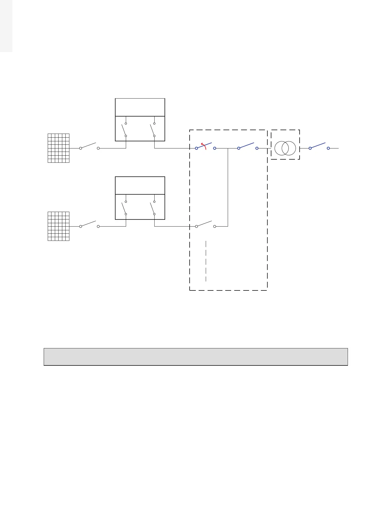
5. Operations on External AC switches
The diagram below represents a possible arrangement of the PV plant. Depending on the design choices
made by the developer of the plant some of the devices could not be present. Identify the external AC
switch(es) in the plant with the support of the plant manager.
PV Strings
External DC
Switch
Internal DC
Switches
Internal AC
Switch
PVS-175-TL
(Unit under service)
PWRMOD
WBOX
OPEN+LOTO
PV Strings
External DC
Switch
Internal DC
Switches
Internal AC
Switch
PVS-175-TL
PWRMOD
WBOX
External LV
AC Switch
External Main LV
AC Switch
External LV
AC Switch
LV Distriubution
Panel
MW Switch
LV/MW
Transformer
•
Open the external AC disconnect switch or the main external AC disconnect switch (blue in previous
picture) outside the inverter (IEC 60364-7-712.536.2.2). In case none of the LV AC switches are present,
the MV switch must be opened.
• Affix designated lock preventing operation onto any external AC disconnect device, affixing designated
tags (LOTO procedure).
NOTE – D Identification of the external switch may require the cooperation of the plant manager
and it must be included in the switching plan defined during the preparation of the work.
•
Check on the status LEDs (08) the shutdown command has been carried out (Missing Grid status):
- Power LED (Green): Flashing
- Alarm LED (Yellow): ON (solid)
- GFI LED (Red): OFF
- WLAN/LAN LED (Blue): Depends by the communication status.

 Loading...


