80 Product manual - PVS-175-TL;A.1 Version
EN
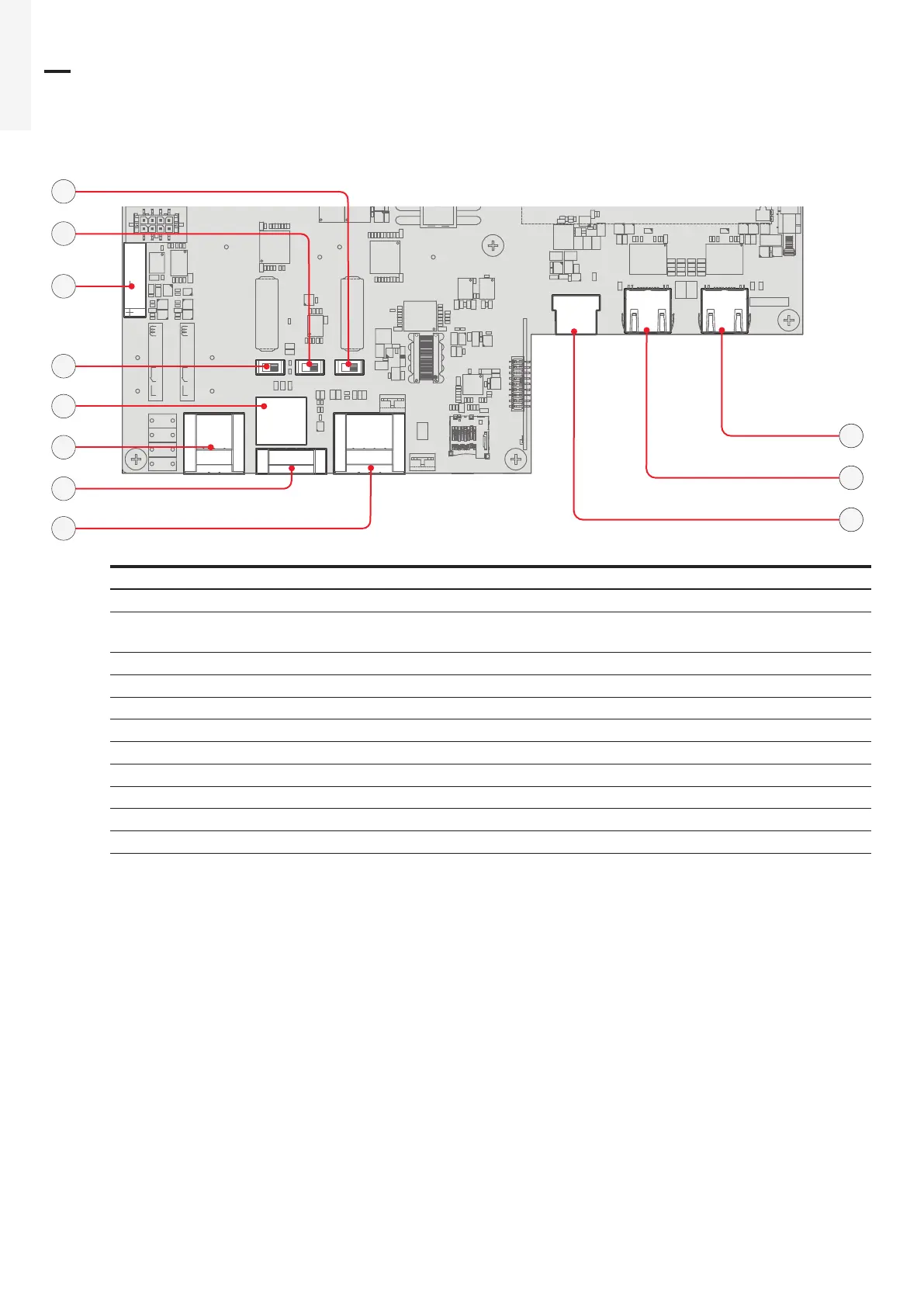
5.9 Connection of the communication and control signals
5.9.1 Communication and control board references
J9 J10
X2
J2
S2
J4
J1
S1 S3
J3
J6
47
37
41
39
40
42
38
42
46
44
45
Terminal name Terminal reference Description
J4 37
ABB RS485 service Ethernet connector (RJ45) (ABB service only)
S2 38
RS485 ABB service 120Ohm termination resistance selector
switch (ABB service only)
S1 39 DRM0 activation switch
S3 40 RS485 line 120Ohm termination resistance selector switch
J2 41
Connection to the multifunction relay (ALARM terminal block)
J1 42 Remote ON/OFF terminal block
J3 43 RS485 line terminal block
J9 44 Ethernet connector 2 (RJ45)
J10 45 Ethernet connector 1 (RJ45)
J6 46 USB connector
X2 47 CR2032 Coin battery
(*) The RS-485 connector (RJ45) (ABB Service only) (37) and the signal R1 on the Remote ON/OFF terminal block (38) are used to
bring the signals on the external connector RS-485&Rem.ON/OFF (Service only) (56).