81Installation
EN
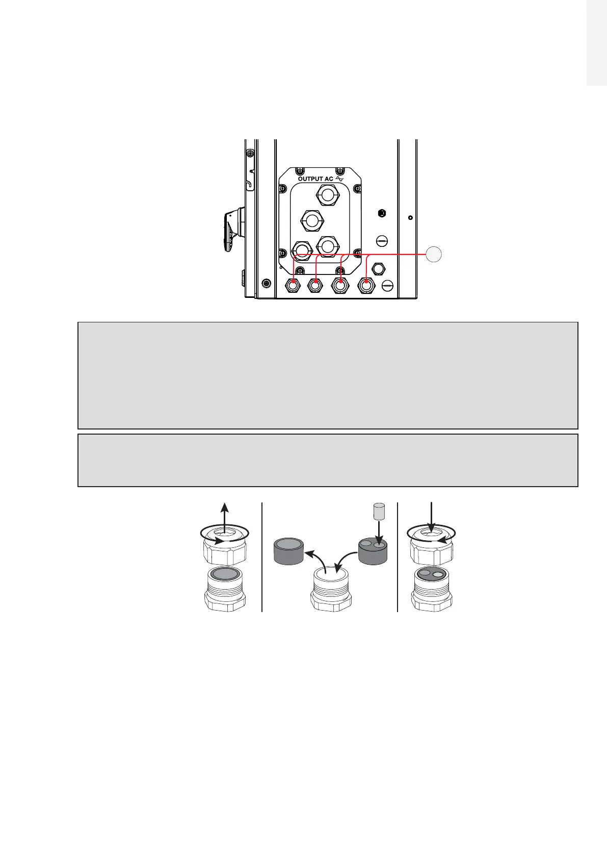
5.9.2 Connections to the communication and control board
The communication and control signals cables must be connected to the communication and control
board (26) inside the wiring box. To reach the board, on the right side of the wiring box, there are:
2x PG16 cable glands (cable range accepted 10-14mm) (13)
2x PG21 cable glands (cable range accepted 13-18mm) (13)
13
ATTENTION – A The connection of the communication and control signal cables should be done
with no over-length of the above mentioned cables. Moreover the communication and control
signal connection cables should not be in contact with live parts.
ATTENTION – A Please ensure that all unused cable glands (13) are properly sealed by the IP65
plastic cap (pre-installed on cable glands).
ATTENTION – A Check the tightness of the signal cable glands (13) (5 Nm PG16 cable gland / 7.5
Nm PG21 cable gland) at the end of wiring operations.
NOTE – D As an alternative, the standard gasket of the PG21 cable glands can be replaced with
the two-hole gasket (supplied in the wiring box installation kit), that accepts two separate
cables with a diameter of 6mm. If a hole is not used, it is necessary to install a plug (supplied
plastic cylinder) to ensure the inverter’s sealing.