82 Product manual - PVS-175-TL;A.1 Version
EN
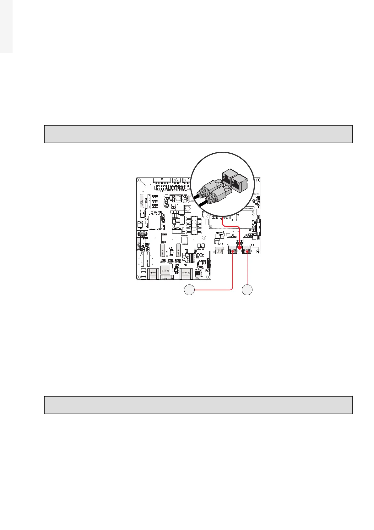
5.9.3 Ethernet connection
The Ethernet connection allows a direct data transfer to the ABB server for monitoring purpose. When the
inverter will be powered on, network parameters are automatically set and the inverter starts the
transmission of telemetry data to the Aurora Vision® CLOUD platform.
The connection of the Ethernet communication cable must be made on the specific connectors (44)(45)
located on the Communication and control board (26).
The two RJ45 connectors LAN1 and LAN2 are equivalent to each other and can be used for the input or for
the output of the line when connecting multiple inverters in a daisy-chain.
NOTE – D If the inverters need to be connected in daisy chain or ring configuration use both
connectors.
J10J9
X1
J6
J1
J4
S2 S1 S3
J7 J8
J20
X2
J2
J3
1
18
2 3 4
1 4
18
7
82
1
44 45
The cable should be compliant to the following specification:
•
Cable type: Patch or Cross type, 100BaseTx, CAT5e (or higher). For outdoor application and/or in presence
of strong electromagnetic sources it is advisable to use shielded cables with metallic shielded RJ-45
plug.
• UV-resistant if used outdoors
• Type of plug: metallic shielded RJ45.
• The maximum length that can reach these cables is 100 meters, and it is always advisable not to pass
them with the power cords in order to avoid interference with data transmission.
• Maximum inverters number connected over one single daisy chain is 40.
ATTENTION – A For outdoor application and/or in presence of adverse weather/strong
electromagnetic events it is advisable to use additional overvoltage protective devices.