86 Product manual - PVS-175-TL;A.1 Version
EN
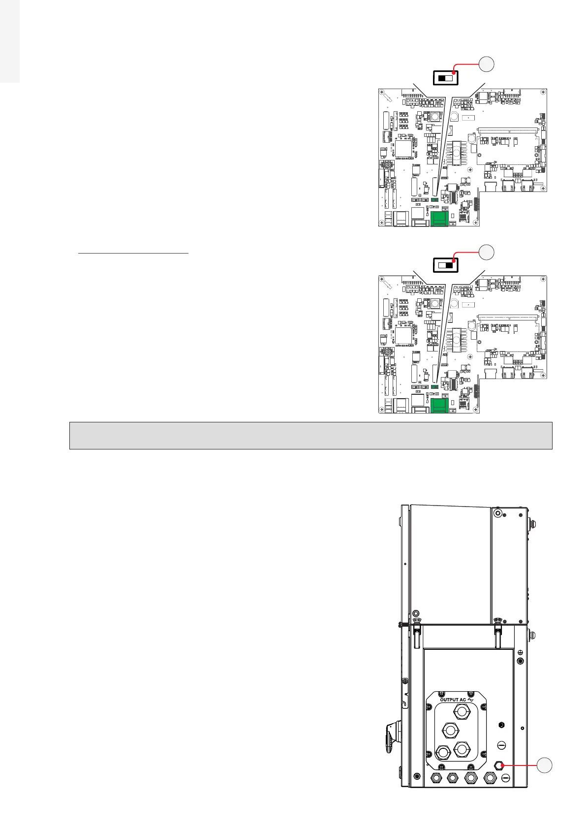
•
When connecting a single inverter to the monitoring system,
activate the communication line resistance terminal by setting
the switch (40) (to the ON position).
• Set a different RS485 address on each inverter in the chain. No
inverter can have “Auto” as an address. An address can be freely
chosen between 2 and 63.
The setting of the address on the inverter is done through the
Web User Interface (“CONNECTIVITY > RS485” refer to paragraph
“CONNECTIVITY menu”).
•
When an RS-485 connection is being used, if one or more
inverters are added to the system at a later time, it is necessary
to remember to reset to OFF the switch of the termination
resistance being used on the inverter which previously was the
last in the system.
NOTE – D Each inverter is shipped with the RS485 address pre-set to “2” and with the resistance
terminal setting Switch (40) in the OFF position.
5.9.5 RS485 RJ45 external connector for ABB Service operation
The inverter has an second RS485 communication lines (that
could be access using the external RJ45 connector (14)) working
as Slave to be used by ABB Service personnel only.
This communication port is configured for communicating over
proprietary communication protocol called “Aurora”.
J9 J10
X2
J2
S2
J4
J1
S1 S3
J3
J6
J9 J10
X2
J2
S2
J4
J1
S1 S3
J3
J6
Monitoring
system
ON
OFF
120.0
TERM.
RS485
ON
OFF
S3
ON
OFF
S3
ON
OFF
S3
ON
OFF
S3
ON
OFF
S3
40
40
14
 Loading...


