87Installation
EN
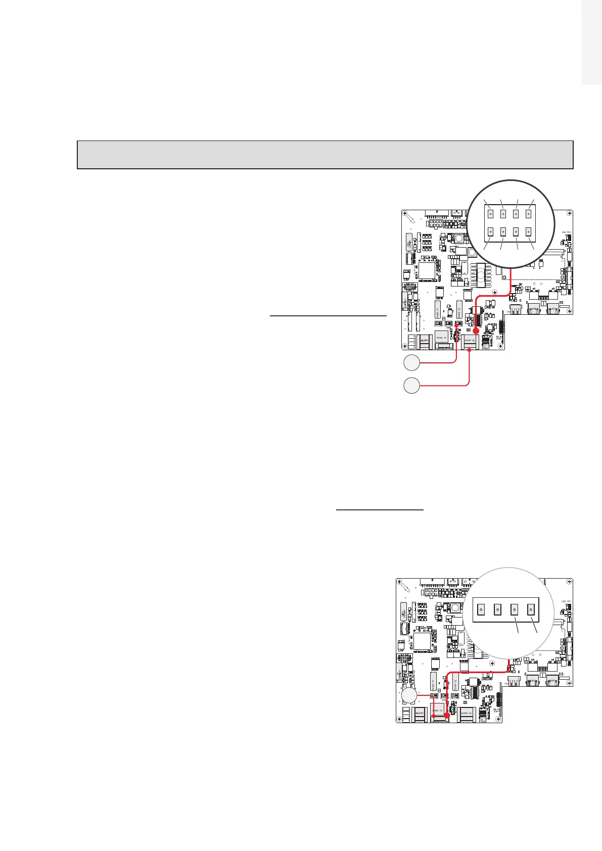
5.9.6 Serial communication connection (RS485 - Master mode)
The RS485 port can either be used for connecting supported accessories (like weather station): in this
case data from accessories will be logged and transferred to the cloud by inverter itself (master mode).
This will allow the inverter to serve as a logger for ABB accessories.
NOTE – D For more information on connecting the accessories to the RS485 terminal block,
refer to the accessory product manual or contact ABB customer support.
•
Connection of the R485 communication line is made using the
terminal block connectors (43) (485+, 485-, RTN and SHIELD).
•
Set the switch of the termination resistance (40) to“ON”
position.
•
When an accessory is connected it must be added and configured
into the “Monitored device” list on the Web User Interface
(“CONNECTIVITY > RS485” refer to “CONNECTIVITY menu”
paragraph to further information).
5.9.7 Remote control connection
The connection and disconnection of the inverter from the grid can be controlled through an external
control by enabling the Remote ON/OFF function on the relevant section of web user interface (“SETTINGS
> INVERTER PARAMETERS > DIGITAL INPUTS”, refer to “SETTINGS menu” paragraph).
If the remote control function is disabled, the switching on of the inverter is dictated by the presence of
the normal parameters that allow the inverter to connect to the grid.
When the functionality is active the switching on of the inverter,
besides being dictated by the presence of the normal parameters
that allow the inverter to connect to the grid, also depends on the
state of the R2 terminal compared to the RTN terminal present on
the terminal block (42) of the communication and control board
(26).
When the R2 signal is brought to the same potential as the RTN
signal (i.e. by making a short circuit between the two terminals of
the connector), this causes the inverter to disconnect from the
grid.
Since this is a digital input, there are no requirements to be
observed as regards cable cross-section (it only needs to comply
with the sizing requirement for passing cables through the cable
glands and the terminal connector).
The external switch used for Remote ON/OFF should be rated for DC low voltage, low current application
(the minimum switching current capability should be 1mA or lower).
J10J9
X1
J6
J1
J4
S2 S1 S3
J7 J8
J20
X2
J2
J3
1
18
2 3 4
1 4
18
7
82
1
485+ RTN485-
485+ RTN
SHIELD
SHIELD485-
40
43
J10J9
X1
J6
J1
J4
S2 S1 S3
J7 J8
J20
X2
J2
J3
1
18
2 3 4
1 4
18
7
82
1
42