88 Product manual - PVS-175-TL;A.1 Version
EN
5.9.8 Multifunction Relay connection (ALARM and AUX)
The inverter is equipped with 2 multifunction relays terminal
blocks (41) with configurable activation. It can be connected with
normally open contact (being connected between the NO terminal
and the common contact C) and with normally closed contact
(being connected between the NC terminal and the common
contact C).
This contact can be used in different operating configurations
that can be selected by accessing the relevant section in the web
user Interface “SETTINGS > Digital Outputs” (“SETTINGS menu”).
Different types of devices (light, sound, etc.) can be connected to the relay, and they need to comply with
the following requirements:
Alarm terminal block requirements
Alternating current Maximum Voltage: 160 Vac / Maximum Current: 6 A
Direct current Maximum Voltage: 30 Vdc / Maximum Current: 3 A
Cable requirements Conductor cross-section: from 28 to 16 AWG
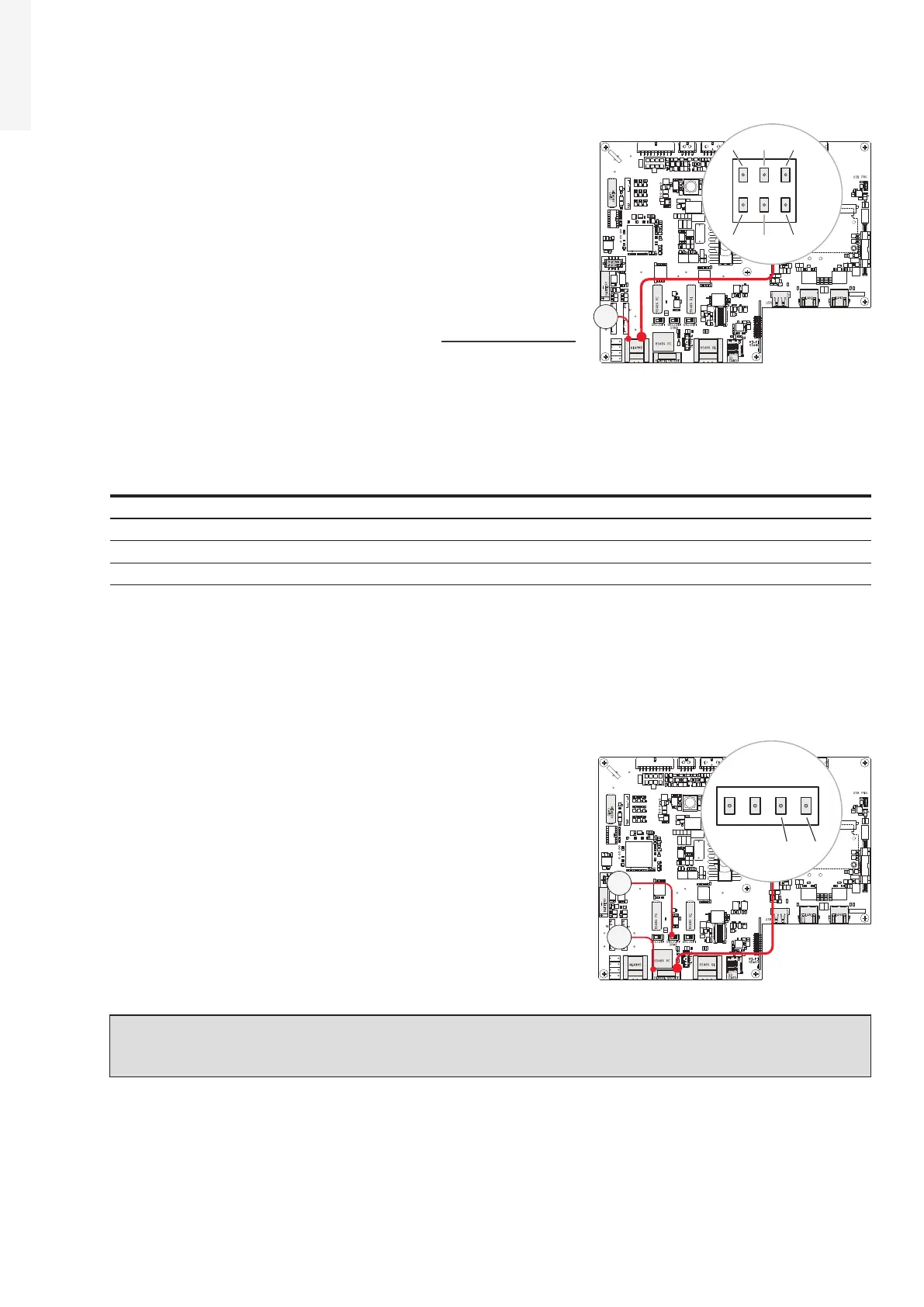
5.9.9 Demand Response Mode 0 (AS/NZS 4777.2)
Where requested by the AS/NZS 4777.2 standard, it’s possible to
use the Remote terminal block (42) for the Demand Response
Mode 0 (DRM0) functionality.
The function could be activated by setting the DRM0 activation
switch (39) to “ON” position.
The terminals to be used to connect the inverter to the distribution
grid are R2 and RTN.
NOTE – D In case of the DRM0 function is activated without the proper wiring of the Remote
terminal block (42), the inverter will no longer be able to connect to the grid. For further
information regarding the DRM0 function refer to the AS/NZS 4777 standard.
J10J9
X1
J6
J1
J4
S2 S1 S3
J7 J8
J20
X2
J2
J3
1
18
2 3 4
1 4
18
7
82
1
N.C N.OC
N.C. N.O.C
AUX
ALARM
41
J10J9
X1
J6
J1
J4
S2 S1 S3
J7 J8
J20
X2
J2
J3
1
18
2 3 4
1 4
18
7
82
1
42
39