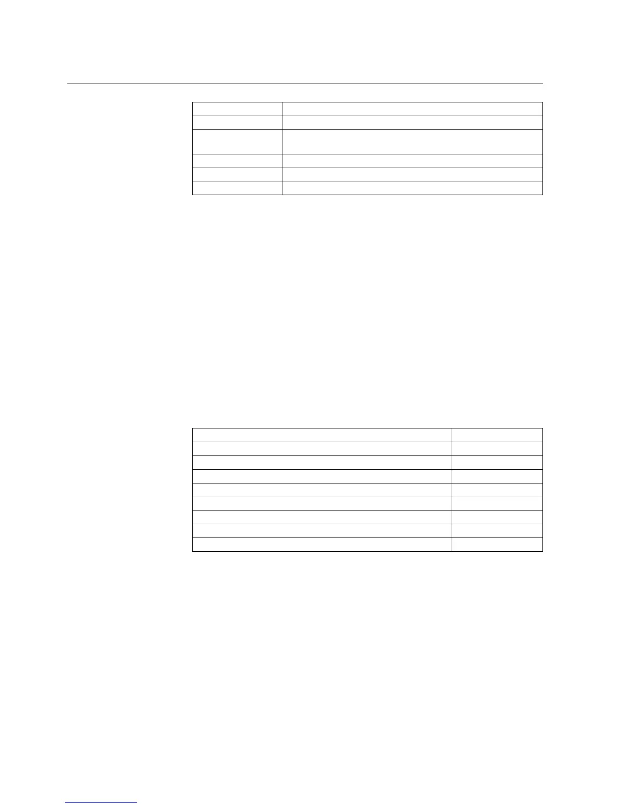
Fault code Type of fault
104 Faulty configuration set (for IEC 60870-5-103)
131, 139, 195, 203,
222, 223
Internal reference voltage error
240 Faulty input, Light sensor 2
241 Faulty input, Light sensor 1
253 Error in the measuring unit
a)
Can be corrected by restoring factory settings for CPU.
b)
All settings will be zero during the fault.
For further information on internal relay faults, refer to the Operator’s Manual.
Warnings
In case of a warning, the relay continues to operate except for those protection
functions possibly affected by the fault, and the green indicator LED (ready)
remains lit as during normal operation. Further, a fault indication message, which
depending on the type of fault includes a fault code, appears on the LCD. If more
than one type of fault occur at the same time, one single numeric code which
indicates all the faults is displayed. The fault indication message cannot be manually
cleared but it disappears with the fault.
When a fault appears, the fault indication message is to be recorded and stated when
ordering service. The fault codes are listed in the following table:
Table 5.1.18.-2 Warning codes
Fault Weight value
Battery low 1
Trip-circuit supervision
a)
2
Power supply module temperature high 4
Communication module faulty or missing 8
DNP 3.0 configuration error
b)
16
DNP 3.0 module faulty 32
Continuous light detected by Light sensor 1 or 2
a)
64
∑ 127
a)
The external fault warning can be routed to SO2 with SGF1/8.
b)
Can be corrected by restoring factory settings for DNP
For further information on warnings, refer to the Operator’s Manual.
5.1.19. Relay parameterization
The parameters of the relay can be set either locally via the HMI or externally via
serial communication with Relay Setting Tool.
134
REF 610REF 610
Feeder Protection Relay
Technical Reference Manual
1MRS755310