143
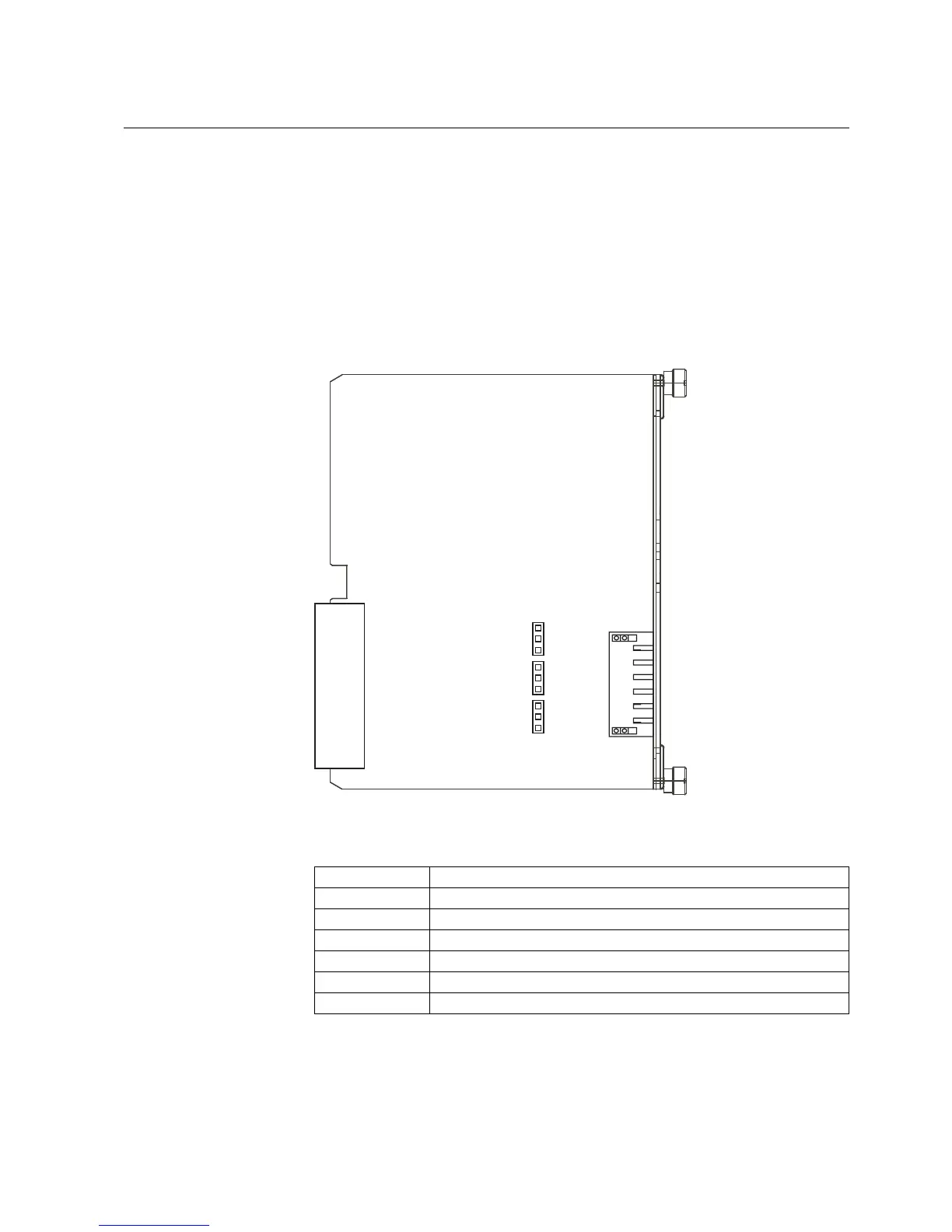
module. The termination resistor is selected by setting jumper X5 to the ON
position. If the internal termination resistor of 120 Ω is used, the impedance of the
cable should be the same.
The bus is to be biased at one end to ensure fail-safe operation, which can be done
using the pull-up and pull-down resistors on the communication module. The pull-
up and pull-down resistors are selected by setting jumpers X3 and X4 to the ON
position.
The jumpers have been set to no termination (X5 in the OFF position) and no
biasing (X3 and X4 in the OFF position) as default.
X3
X4
X5
off
on
off
on
off
on
A040334
Fig. 5.2.3.-1 Jumper location on the RS-485 communication module
Table 5.2.3.-2 RS-485 rear connector
Terminal Function
X5.5-6 Data A (+)
X5.5-5 Data B (-)
X5.5-4 Signal GND (for potential balancing)
X5.5-3 -
X5.5-2 Shield GND (via capacitor)
X5.5-1 Shield GND
Feeder Protection Relay
Technical Reference Manual
REF 610REF 610
1MRS755310