63
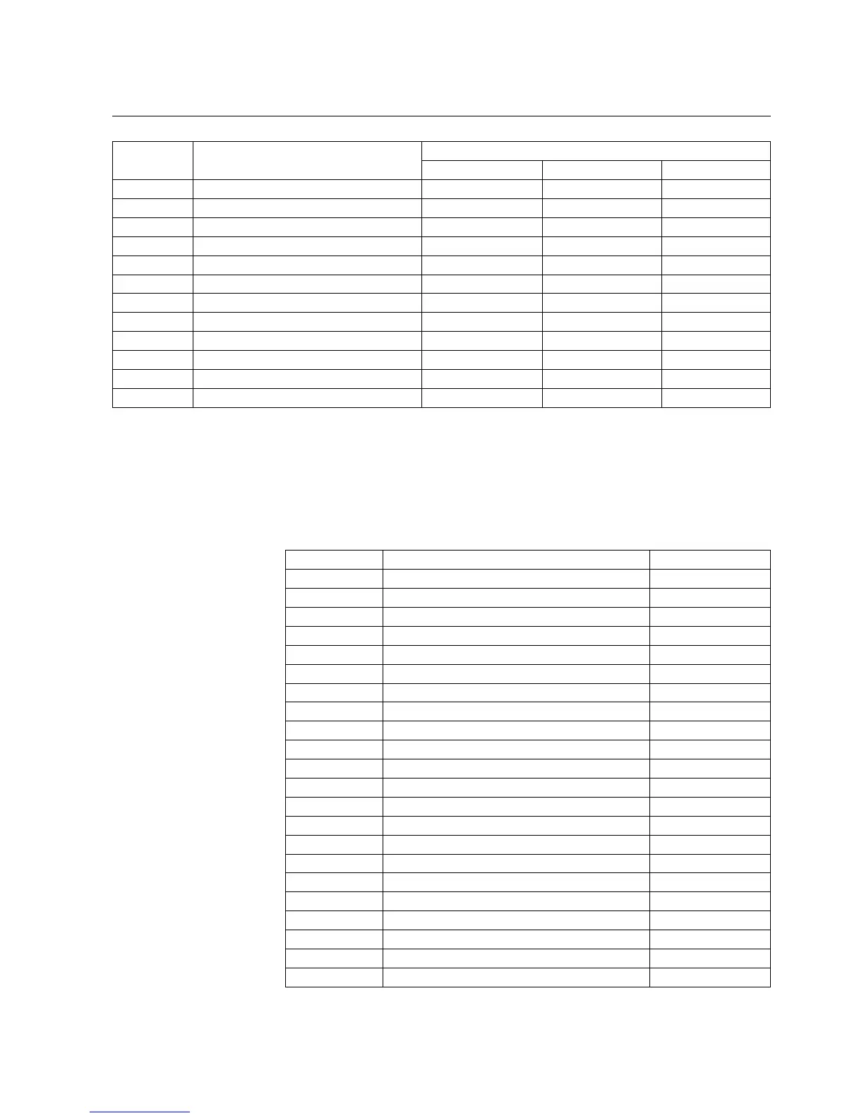
Switch Function Default setting
SGR1...SGR3 SGR4...SGR5 SGR6...SGR8
SGR1...8/13 Alarm signal from stage θ>000
SGR1...8/14 Trip signal from stage θ>100
SGR1...8/15 External trip signal 0 0 0
SGR1...8/16 Open CB command from AR 0 0 0
SGR1...8/17 Close CB command from AR 0 0 0
SGR1...8/18 Definite trip alarm signal from AR 0 0 0
SGR1...8/19 CB reclosing failed signal from AR 0 0 0
SGR1...8/20 Shot due signal from AR 0 0 0
SGR1...8/21 Lockout signal from AR 0 0 0
SGR1...8/22 Trip signal from stage ARC 1 0 0
SGR1...8/23 Light signal output 0 0 0
ΣSGR1...8 2108074 5461 0
a)
If the optional I/O module has not been installed, dashes are shown on the LCD and “9999” when the parameter is read via the SPA bus.
SGL1...SGL8
The signals are routed to LED1 with the switches of switchgroup SGL1, to LED2
with those of SGL2, and so forth.
Table 5.1.4.10.-9 SGL1...SGL8
Switch Function Default setting
SGL1...8/1 Trip signal from stage I> 0
SGL1...8/2 Trip signal from stage I>> 0
SGL1...8/3 Trip signal from stage I>>> 0
SGL1...8/4 Trip signal from stage I
0
>0
SGL1...8/5 Trip signal from stage I
0
>> 0
SGL1...8/6 Trip signal from stage ΔI> 0
SGL1...8/7 Alarm signal from stage θ>0
SGL1...8/8 Trip signal from stage θ>0
SGL1...8/9 Trip lockout signal 0
SGL1...8/10 Definite trip alarm signal from AR 0
SGL1...8/11 Shot due signal from AR 0
SGL1...8/12 Lockout signal from AR 0
SGL1...8/13 CB position open 0
SGL1...8/14 CB position closed 0
SGL1...8/15 DI1 signal 0
SGL1...8/16 DI2 signal 0
SGL1...8/17 DI3 signal 0
SGL1...8/18 DI4 signal 0
SGL1...8/19 DI5 signal 0
SGL1...8/20 Trip signal from stage ARC 0
SGL1...8/21 Light signal output 0
SGL1...8/22 Trip signal from CBFP 0
Feeder Protection Relay
Technical Reference Manual
REF 610REF 610
1MRS755310