Multifunction Protection and Switchgear Control unit REF542plus
Manual: Motor Protection with ATEX-Certification
4.3.2 Functional check
For checking the function of this monitoring the number of starts, it is recommended
to use single- or three-phase testing equipment for load simulation in the thermal pro-
tection function. Dependent on the temperature calculated by the thermal protection,
the number of starts in cold condition or in warm condition can be tested. The func-
tional check of the thermal protection is described in the following paragraph.
4.4 Thermal overload protection
For motor protection, the thermal overload protection based on the thermal replica is
one of the major functions for supervising the motor for temperature violations on ac-
count of overloads during operation. In the REF542plus, a thermal replica with a total
memory function has been implemented in accordance with the applicable standard
[DIN1]. In the following, the thermal replica and the setting options are dealt with.
For simulating the temperature rise in the motor, a thermal homogenous-body model
with losses is assumed. The figure 5 below illustrates the principle of the model.
Thermal Loss
Thermal
Energy
Thermal Storage
(Memory)
Figure 5: Thermal homogenous-body model with losses
On account of the loads present during the operation conditions, the load current in
the motor can be taken as a measure for the quantity of energy, which feed the tem-
perature rise in the motor. The size of the thermal energy is proportional to the square
value of the load current. Due to the existing motor cooling a portion of the thermal
energy will be discharged in the form of energy loss. The rest of the thermal energy is
stored in the motor. The size of the stored energy is proportional to the motor tem-
perature.
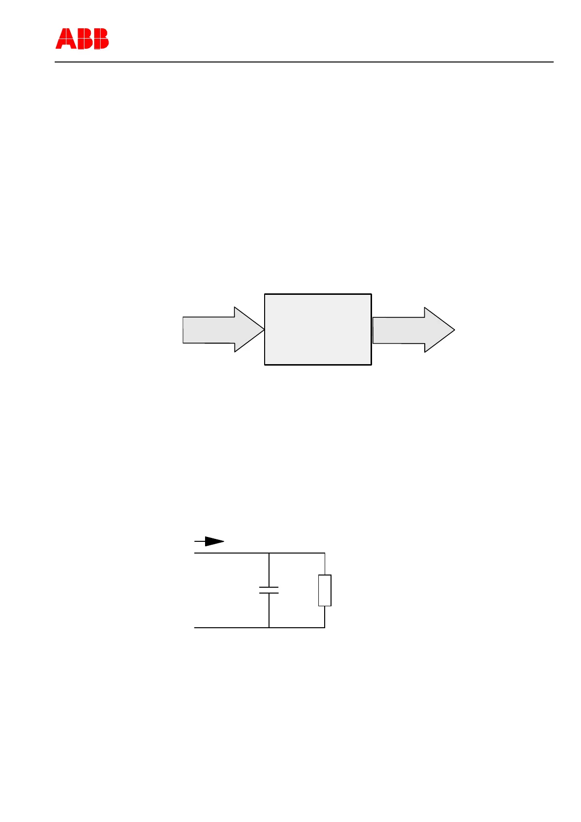
For calculating the motor temperature, the above-mentioned thermal model can be
simulated by a simple electrical circuit. The next figure shows the circuit diagram.
CR
I
Figure 6: Circuit diagram for determining the motor temperature
From the circuit diagram, the following analogy is obtained:
The energy flow is proportional to charging current for the capacitor
The thermal capacity is simulated by capacitor C
1VTA100114-Rev. 04 en PTMV, 19.01.05 Motorprotection 17 / 66
Valid from Version V4D02