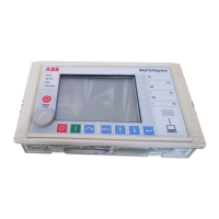
Multifunction Protection and Switchgear Control unit REF542plus
Manual: Motor Protection with ATEX-Certification
9.2 Binary inputs and outputs
Each Binary I/O module has the following number of inputs and outputs:
9.2.1 BIO module with mechanical output relays (version 3)
14 input channels Possible auxiliary voltage ranges:
• 20 to 90 V DC (threshold 14 V DC)
• 80 to 250 V DC (threshold 50 V DC)
Each input has a fixed filter time of 1 ms. Additional filter
time can be configured by software.
6 power outputs (channels
BO 1 to 6).
Maximum operating voltage 250V AC/DC
Make current 8 A
Load current 6 A
Breaking capacity:
1 Contact 75 Watt
2 Contacts 300 W
at L/R <15 ms
Operating time 8 ms
2 signal outputs (BO7 and 8)
and 1 Watchdog output (WD)
Maximum operating voltage 250 V AC/DC
Load current 2 A
Operating time 8 ms
Optional: 1 Static signal out-
put on BO7
Maximum operating voltage 250 VDC
Make current 1.5 A (100ms)
Load current 0.7 A continuous
R
Ein
1,06 Ω
R
Aus
40 MΩ
Operating time 1 ms
Coil supervision circuit 1 for channel BO2,
to be supervised impedance ≤ 10 kΩ
1VTA100114-Rev. 04 en PTMV, 19.01.05 Motorprotection 56 / 66
Valid from Version V4D02

 Loading...