Multifunction Protection and Switchgear Control unit REF542plus
Manual: Motor Protection with ATEX-Certification
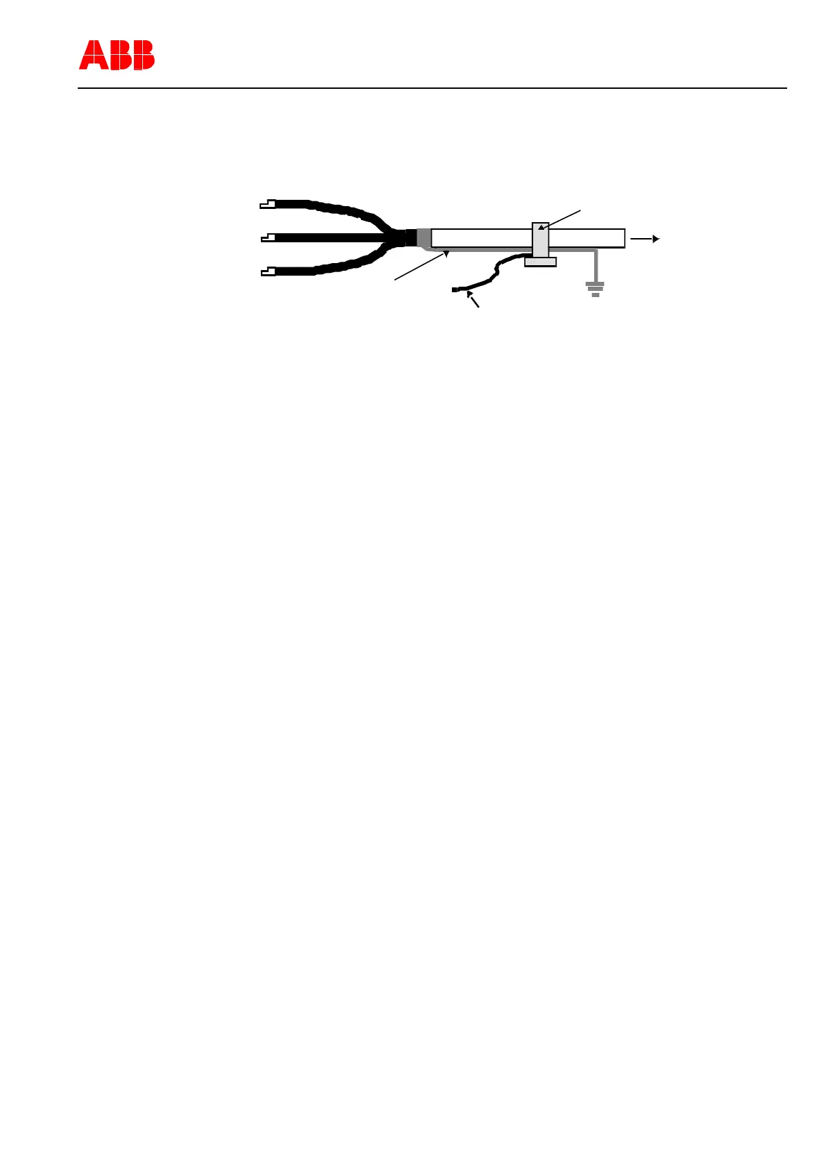
This enables weak ground faults currents that flow along the cable sheath to dissi-
pate. In this way, they will not be incorrectly measured at their own relay feeder. The
following shows another view of the cable current transformer grounding.
Cable current transformer
Shielding
Out-fee
Secondary measurement line
Figure 21: Grounding of a cable current transformer
7.2.3.2 Check the voltage transformer circuits
To check that the voltage transformer and the voltage transformer circuits are wired
correctly, run the following checks:
Polarity check
Wiring check
Check the transformer circuit grounding
Check the voltage transformer for neutral point-ground voltage (when used).
To measure ground faults please proceed as follows: The voltage is referred to as
neutral point-ground voltage of a ground fault measurement when it occurs with a me-
tallic ground fault in the network between terminals "e“ and "n“ of the open delta wind-
ing.
In the event of a metallic ground fault in phase L1, the external phase-to-neutral volt-
ages occur in phases L2 and L3 instead of the conductor-ground voltages. They are
added geometrically and yield three times the amplitude between terminals "e“ and
"n“.
7.2.3.3 Checking the auxiliary voltage
The auxiliary voltage must be in the tolerance range of the power supply module and
have the proper polarity under all operating conditions.
7.2.3.4 Check the tripping and signaling contacts
Conduct this check as shown in the bay documentation.
7.2.3.5 Check the binary inputs
Check the polarity and the voltage value of the binary inputs on the REF542 in accor-
dance with the technical data of the binary inputs.
7.2.4 Grounding of the REF542plus
As can be seen in the following figure, the power supply board at connector X10 must
be grounded to the housing. Therefore the middle pin must be connected to the
grounding point in the LV compartment. Beside that, the shielding of the cable con-
nection to the HMI control unit must also be connected to ground respectively to the
housing.
1VTA100114-Rev. 04 en PTMV, 19.01.05 Motorprotection 46 / 66
Valid from Version V4D02