Multifunction Protection and Switchgear Control unit REF542plus
Manual: Motor Protection with ATEX-Certification
7.2.5 Typical examples of analog and binary connections
The following pages show examples for wiring analog inputs (measuring inputs) on
the REF542plus with sensors or transducers, binary I/Os and analog output boards.
Typical examples of usage in practice will be shown here. The following symbols are
used in the circuit diagrams:
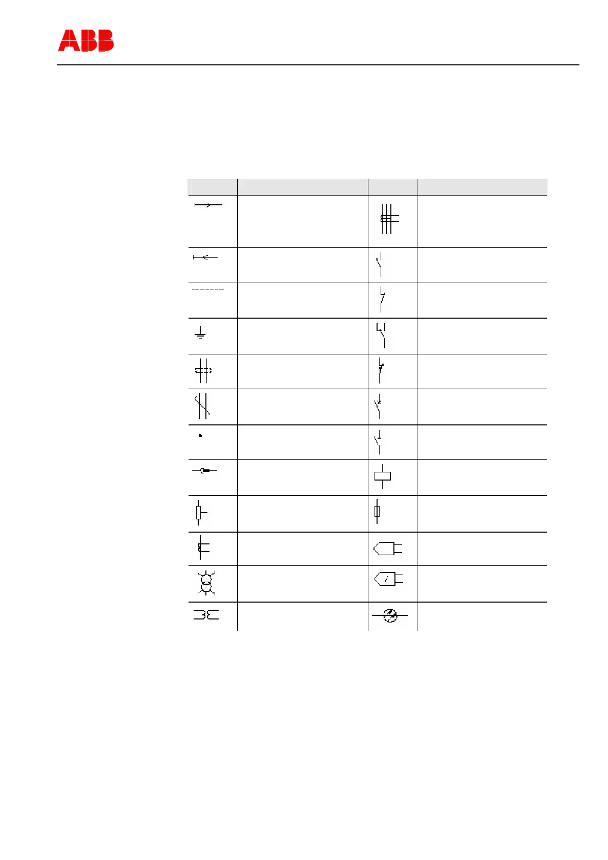
Table 6: Graphical symbols for electric diagram (IEC 60617)
Symbol Legend Symbol Legend
Energy flow from the bus bar
Ring core current transformer
Energy flow towards the bus
bar
Make contact
Mechanical, pneumatic or hy-
draulic connection (link)
Break contact
Earth, ground
Change-over break before
make contact
Conductors in a screened ca-
ble
Position switch, break contact
Twisted conductors
Circuit breaker
Connection of conductors
Disconnector
Plug and socket male and
female)
Operating device
Resistor with one fixed tap-
ping
Fuse
Current transformer
Sensing element
Three-phase transformer
Current sensing element
Voltage transformer
Optical fibre cable
1VTA100114-Rev. 04 en PTMV, 19.01.05 Motorprotection 48 / 66
Valid from Version V4D02