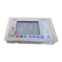
Multifunction Protection and Switchgear Control unit REF542plus
Manual: Motor Protection with ATEX-Certification
9.2.2 BIO module with static outputs
14 inputs (BI 1-14) Auxiliary voltage range
• 48 to 265 VDC (Threshold 35 VDC)
Each input has a minimum fixed filter time of 5 ms. Addi-
tional filter time can be configured by software.
3 power outputs (BO1,2
and 7)
Operating voltage 48 to 250 VDC
Make current 64 A
Load current 16 A
Operating time 1 ms
4 power outputs (BO3 to 6) Operating voltage 48 to 250 VDC
Make current 120 A
Load current 31 A
Operating time 1 ms
2 Signal outputs (BO8,9) and
1 Watchdog output (WD)
Operating voltage 400 VDC
Make current 1.5 A (100ms)
Load current 0.7 A
R
Ein
1,06 Ω
R
Aus
40 MΩ
Operating time 1 ms
Coil supervision circuits 2 for channel BO1 and BO2,
to be supervised impedance ≤ 10 kΩ
9.3 Interfaces
9.3.1 HMI Control Unit:
Optical/electrical standard interface RS 232 to the Notebook PC (at the front)
Electrical isolated standard interface RS 485 to the Base Unit (at the rear)
9.3.2 Base Unit:
Electrical isolated standard interface RS 485 to the HMI
Electrical standard interface RS 232 for service purposes
9.4 Analog output board (optional)
Four channel 0 to 20 mA or 4 to 20 mA
9.5 Analog input board (optional)
Six channel 4 to 20 mA
9.6 Communication (optional)
SPABUS, optical interface, optional with SMA or ST connector, for plastic or
glass fiber (multi mode)
LON (according to ABB LAG1.4), optical interface with ST connector for glass
fiber (multi mode)
1VTA100114-Rev. 04 en PTMV, 19.01.05 Motorprotection 57 / 66
Valid from Version V4D02

 Loading...