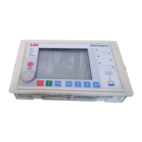
Multifunction Protection and Switchgear Control unit REF542plus
Manual: Motor Protection with ATEX-Certification
u
ut
u
up
I
I
I
I
t
ϑϑ
ϑϑ
ϑϑ
ϑϑ
τ
−
−
−
⎟
⎟
⎠
⎞
⎜
⎜
⎝
⎛
−
−
−
⎟
⎟
⎠
⎞
⎜
⎜
⎝
⎛
=
Mn
2
Mn
Mn
2
Mn
ln
(7.)
Where:
I Actual loading current in the motor
I
Mn
Nominal motor current as a reference variable
ϑ
p
Initial temperature due to preloading
ϑ
u
Ambient temperature as a reference variable
ϑ
Mn
Rated motor temperature when loaded with rated current
ϑ
t
Motor temperature reached after a certain time span
In the applicable standard [DIN1], the characteristic is specified by the equation be-
low:
22
22
)(
ln
B
p
IkI
II
t
−
−
=
τ
(8.)
where
I Loading current in the motor
I
p
Preloading current in the motor
I
B
Basic current or rated current of the motor
k Overload constant within a range of 1 to 1.2
Equation (7) can be transformed and related to the basic or nominal current of the
motor:
2
2
B
2
B
2
B
ln
k
I
I
I
I
I
I
t
p
−
⎟
⎟
⎠
⎞
⎜
⎜
⎝
⎛
⎟
⎟
⎠
⎞
⎜
⎜
⎝
⎛
−
⎟
⎟
⎠
⎞
⎜
⎜
⎝
⎛
=
τ
(9.)
As a result, equation (6) and (8) indicate that the setting for constant
uMn
ut
ϑϑ
ϑϑ
−
−
=k
(10.)
can be derived from the setting for the temperatures. The temperature setting is a
measure for the thermal capacity. The denominator in the root equation above is
equal to the nominal capacity contents under nominal operation condition of the mo-
1VTA100114-Rev. 04 en PTMV, 19.01.05 Motorprotection 19 / 66
Valid from Version V4D02

 Loading...