1. Press an arrow button to access the main menu.
2. Use the arrow buttons to select CONFIGURATION\COMMUNICATION and
press
. The cursor is at the setting currently in use (REAR CONNECTION or
FRONT CONNECTION).
3. Press
to enter the setting mode. The second line starts to flash.
4. Use
or to select the wanted setting.
5. Press
to confirm the selection.
6. Press
to return the display to the idle mode.
When the front connection has been selected and there is no communication for
approximately five minutes, the rear connection is automatically activated. To keep
the front connection continuously active, press
and simultaneously when
connecting the auxiliary voltage to the relay.
When the rear connection is selected, the selected rear protocol is
automatically activated.
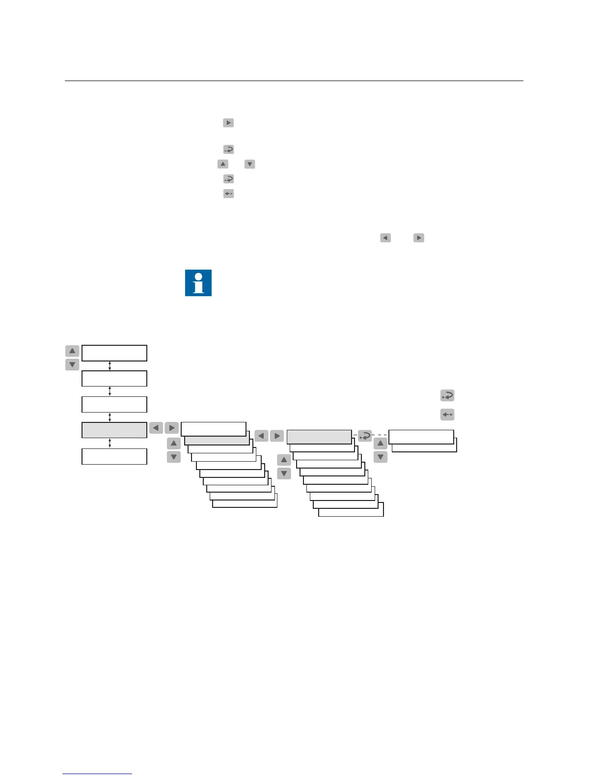
Main Menu
Group Menu
Parameter Menu
SETTINGS
CONFIGURATION
MEASUREMENTS
RECORDED DATA
INFO
FUNCTION TEST/DI
COMMUNICATION
LANGUAGE
FREQUENCY
CONFIGURATION
MEMORY SETTINGS
HMI PASSWORDS
TIME
LINE-IDLE STATE
CONNECTION TYPE
COUNTER :xxx
UNIT ADDRESS :xxx
MODBUS SETTINGS
SPA SETTINGS
REAR PROTOCOL
REAR CONNECTION
CONFIGURATION
IEC103 SETTINGS
FRONT CONNECTION
REAR CONNECTION
CONFIGURATION
Confirm
Cancel
RTD INPUTS
TRIP CIRCUIT SUP
REAR COM. MODULE
STORE COUNTER
A040243_2
Fig. 4.1.10.-1 Switching between the front and rear connections
4.1.10.1. Target LED for front communication
*
Target off: the rear communication is currently selected.
*
Lit target: the front communication port is currently selected.
*
Flashing target: the front communication port is currently selected and the relay
is communicating.
4.1.11. How to select the protocol for rear communication
REM 610 allows you to choose the communication protocol for rear connection.
24
REM 610REM 610
Motor Protection Relay
Operator's Manual - ANSI ve rsion
1MRS755538