41
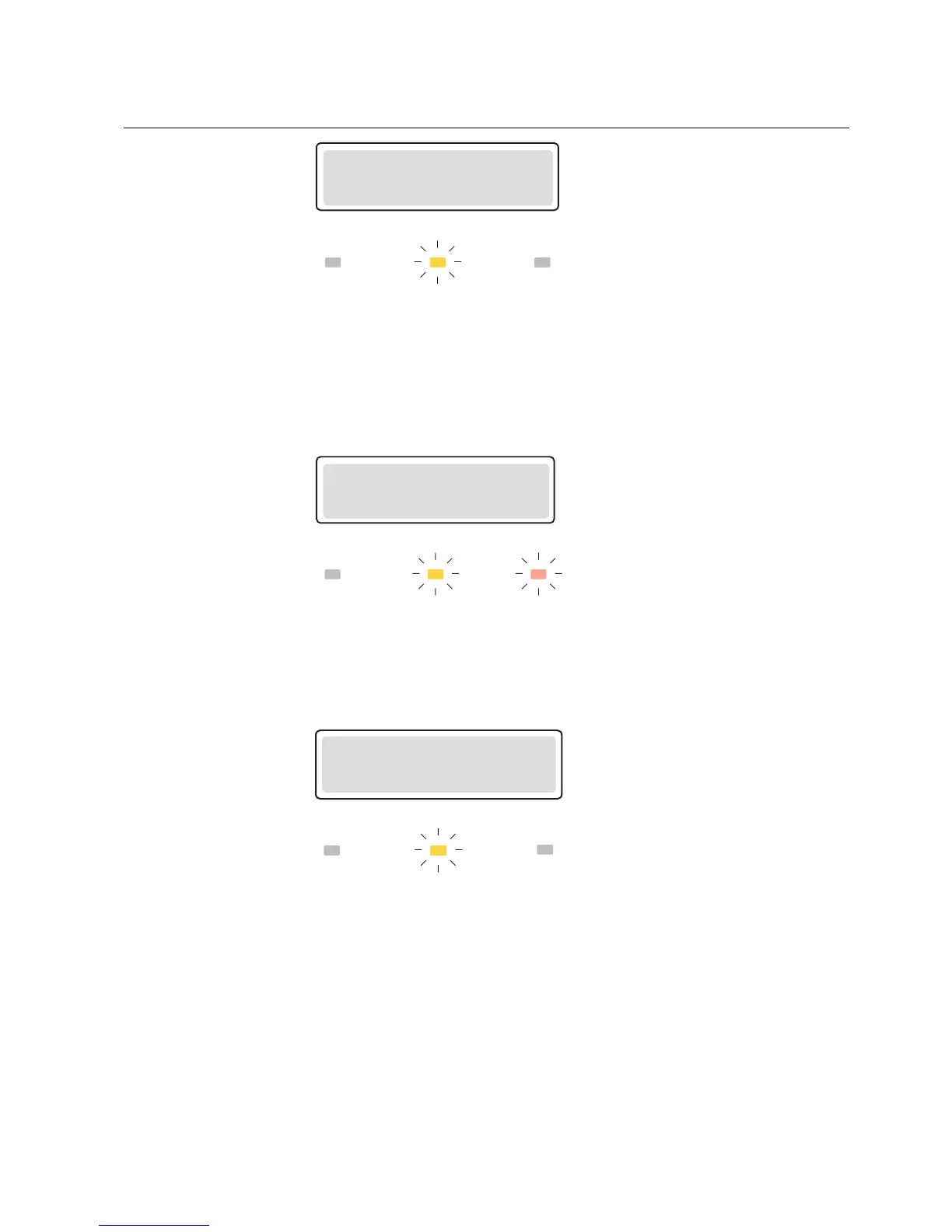
PICKUP
50P la
A070077
Fig. 4.3.2.1.-1 Latching pickup target
When a protection element trips, the text TRIP appears on the display along with
the name of the function. Additionally, the name of the energizing input(s) which
caused the fault are displayed (except for the motor start-up supervision, phase
unbalance, phase reversal, thermal overload and temperature protection). The red
target is lit.
TRIP
50P la/lb
A070078
Fig. 4.3.2.1.-2 Trip target
In case of an alarm from the thermal overload or temperature protection, the text
ALARM appears on the display along with the function symbol and the yellow target
LED is lit.
ALARM
49
A040274
Fig. 4.3.2.1.-3 Alarm target
In case of a restart disable state, the text RESTART DISABLE will appear on the
display. The state will not affect the disable/alarm and trip LEDs, but instead you
can use a programmable LED to indicate the state; refer to section Programmable
target LEDs. The text message for the restart disable state is non-latching, whereas
the status target via a programmable LED can be either latching or non-latching.
The restart of a motor can be disabled by the thermal protection, the cumulative
start-up time counter or an external digital input signal. For the priority of targets for
the restart disable state; refer to section Priority of operation target messages.
Motor Protection Relay
Operator's Manual - ANSI ve rsion
REM 610REM 610
1MRS755538